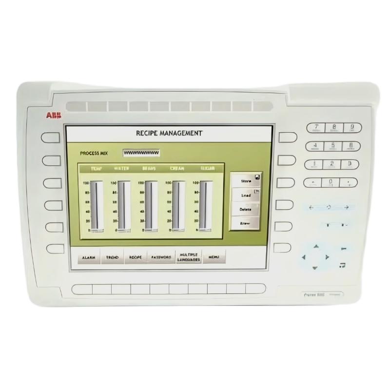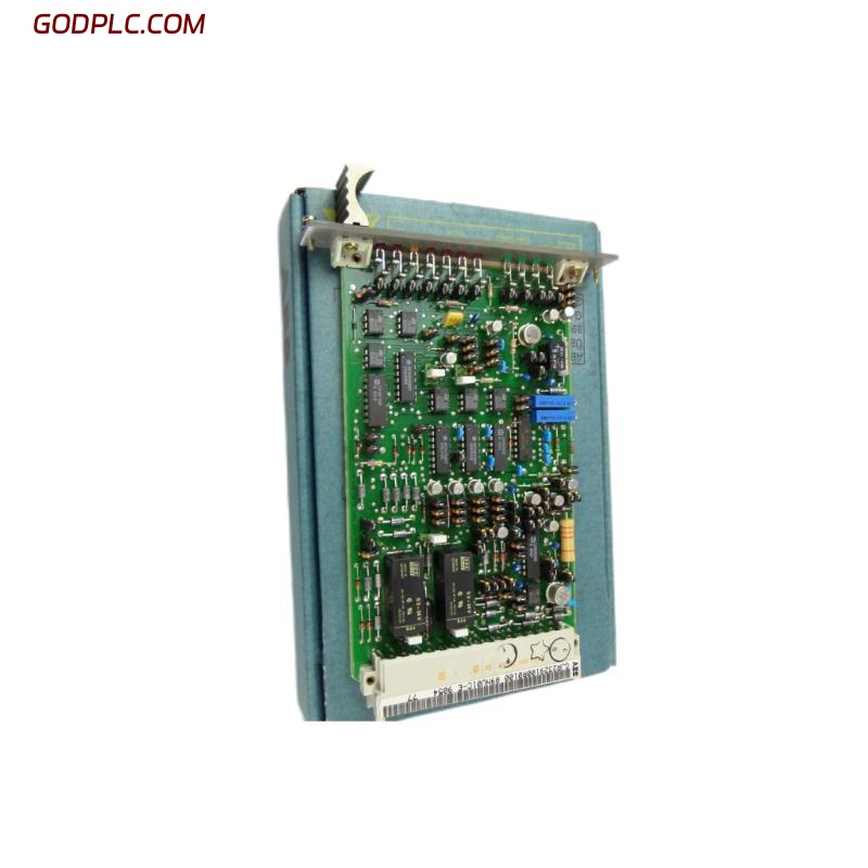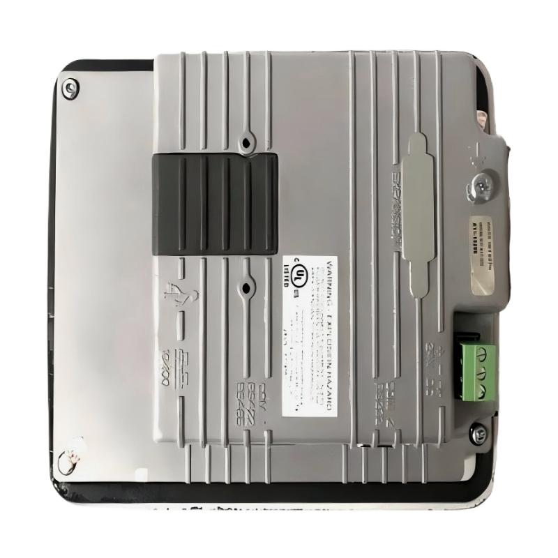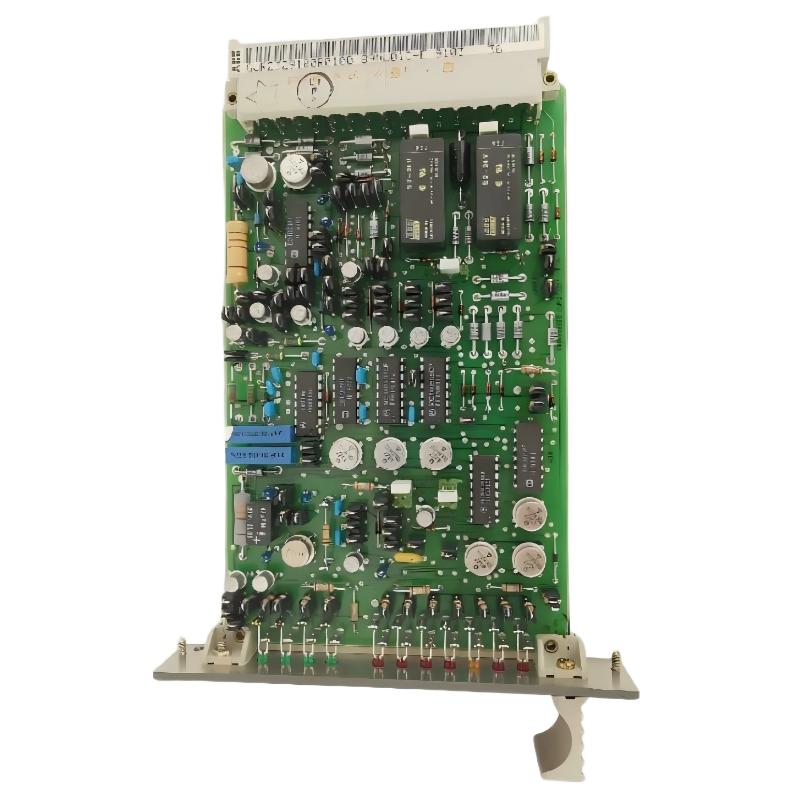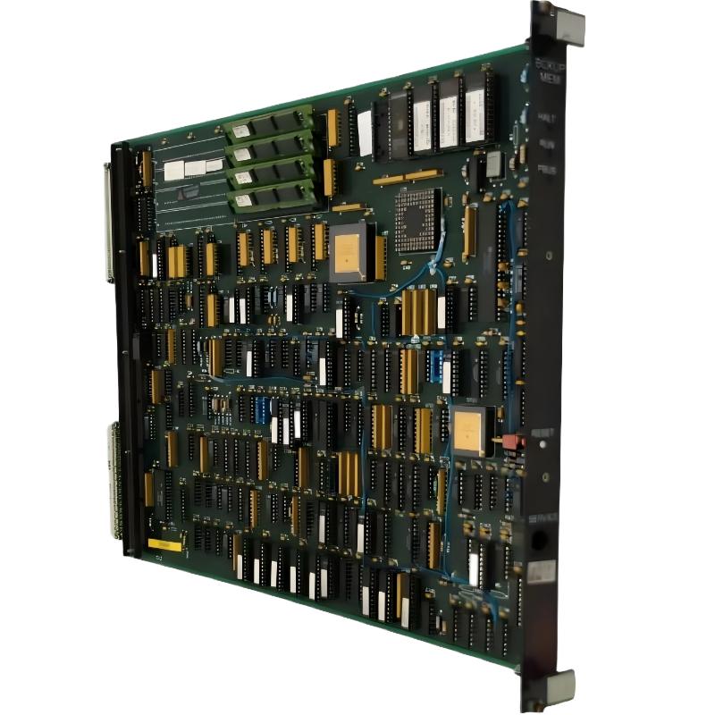
ABB 6214BZ10120C Backup Memory Module Installation Guide Overview
ABB 6214BZ10120C is a 4 MB memory module used in legacy ABB industrial control hardware for retaining backup data and supporting system recovery. During installation, the main engineering concern is not simply inserting the module, but confirming compatibility, memory recognition, configuration integrity, and a successful backup or restore operation.
This ABB 6214BZ10120C Installation Guide focuses on practical Setup and Commissioning checks, including hardware preparation, memory installation, System Configuration, verification, and recovery testing.
ABB 6214BZ10120C Installation and Commissioning Contents
- ABB 6214BZ10120C Hardware Preparation
- ABB 6214BZ10120C Module Compatibility Checks
- ABB 6214BZ10120C Memory Module Installation
- ABB 6214BZ10120C System Configuration and Setup
- ABB 6214BZ10120C Commissioning and Memory Validation
- ABB 6214BZ10120C Field Commissioning Case
- ABB 6214BZ10120C Installation FAQ
- ABB 6214BZ10120C Installation Conclusion
ABB 6214BZ10120C Hardware Preparation
Before installing the ABB 6214BZ10120C Backup Memory Module, record the controller status and existing memory configuration. A backup-memory replacement should be treated as a controlled maintenance operation because an incorrect memory device or incomplete backup can affect recovery procedures.
- Record the controller or host module identification.
- Save the current application and configuration data when the system permits.
- Check the existing memory arrangement before removal.
- Inspect the 6214BZ10120C connector and board surface for contamination or mechanical damage.
- Use appropriate ESD protection during handling.
- Confirm that the replacement part is the intended 6214BZ10120C version.
For legacy control equipment, the safest practice is to document the original memory state before changing hardware. This gives the commissioning engineer a reference point if the controller does not recognize the replacement module immediately.
ABB 6214BZ10120C Module Compatibility Checks
The 6214BZ10120C is commonly identified as a 4 MB memory module. Compatibility should therefore be checked against the actual host controller and its firmware or system revision rather than assumed from physical connector compatibility alone.
During System Configuration review, verify the following:
- Host controller family and hardware revision.
- Memory module type expected by the controller.
- Installed firmware or operating revision.
- Backup and restore procedure supported by the host system.
- Existing application-memory allocation.
Physical insertion does not prove functional compatibility. If the controller detects the module but reports an invalid memory state, stop the commissioning process and investigate configuration or revision compatibility before writing data to the module.
ABB 6214BZ10120C Memory Module Installation
Install the ABB 6214BZ10120C with the host equipment in the maintenance state specified by the applicable system procedure. Avoid removing or inserting memory hardware while the controller is actively writing memory unless the equipment documentation explicitly permits hot replacement.
- Place the control system in the approved maintenance condition.
- Isolate power when required by the host hardware procedure.
- Discharge static electricity using an appropriate ESD method.
- Remove the existing memory module without forcing the connector.
- Inspect the socket and module contacts.
- Align the ABB 6214BZ10120C correctly with the host connector.
- Seat the module evenly and verify that it is mechanically secure.
- Restore the system according to the approved startup procedure.
A common field mistake is to concentrate on mechanical insertion and skip the recognition check. The installation is not complete until the controller confirms the expected memory capacity and operating status.
ABB 6214BZ10120C System Configuration and Setup
After installation, the Setup process should begin with memory recognition rather than immediately restoring an old application. First establish that the controller can communicate correctly with the memory module.
Where the host system provides diagnostic commands or maintenance screens, use them to confirm the detected memory size and status. A generic diagnostic sequence can be represented as:
CHECK CONTROLLER STATUS
CHECK MEMORY DEVICE
READ MEMORY CAPACITY
VERIFY MEMORY STATUS
COMPARE CONFIGURATION
PERFORM BACKUP/RESTORE TEST
The exact command syntax depends on the ABB control platform. The purpose of this sequence is to establish a logical chain: hardware detected → memory capacity correct → memory status valid → configuration accepted → backup function verified.
ABB 6214BZ10120C Commissioning and Memory Validation
Commissioning should include both recognition and functional validation. If the memory module is visible but the backup operation fails, the problem may be related to data structure, access permissions, controller state, or memory initialization rather than the module itself.
- Confirm the controller reaches its normal operating state.
- Confirm the memory module is recognized without a diagnostic alarm.
- Verify the reported memory capacity.
- Perform a controlled backup operation.
- Verify that the backup completes without an error.
- Check that the original control application remains unchanged.
- Record the final controller and memory status.
ABB 6214BZ10120C Field Commissioning Case
In a representative legacy-control commissioning case, a replacement memory module was recognized by the controller but the initial backup operation did not complete. The engineering team did not immediately classify the memory module as defective. Instead, they compared the controller status, memory capacity indication, and configuration state.
The controller correctly identified the installed memory capacity, which shifted the investigation away from connector or hardware recognition problems. The configuration was then checked before a controlled backup was repeated. After the configuration state was corrected and the backup sequence was restarted, the memory operation completed normally.
This type of investigation illustrates an important commissioning principle: when a memory module is detected correctly, Fault Diagnosis should move from physical installation toward configuration and data-handling conditions instead of replacing hardware repeatedly.
ABB 6214BZ10120C Installation FAQ
What is the ABB 6214BZ10120C memory capacity?
The ABB 6214BZ10120C is identified as a 4 MB memory module. The actual usable capacity and function should be confirmed against the host controller’s System Configuration.
Why should the controller configuration be recorded before installing the 6214BZ10120C?
Recording the original configuration provides a reference for troubleshooting if the replacement memory is not recognized or if the backup data cannot be restored correctly.
Can the ABB 6214BZ10120C be inserted while the controller is running?
Do not assume hot insertion is supported. Follow the maintenance procedure specified for the host control system and remove power when the hardware procedure requires it.
What should be checked if the 6214BZ10120C is detected incorrectly?
Check the physical seating, connector condition, host controller compatibility, firmware revision, and memory configuration before concluding that the module has failed.
How can the memory module be validated after installation?
Verify memory recognition and reported capacity first, then perform a controlled backup or restore operation and confirm that no memory-related diagnostic alarm remains.
ABB 6214BZ10120C Installation Conclusion
A successful ABB 6214BZ10120C Installation Guide procedure should end with functional verification, not simply hardware replacement. Correct identification, controlled installation, System Configuration checks, memory recognition, and backup validation provide a reliable Setup and Commissioning sequence for legacy ABB control equipment.
For field engineers, the key point is to separate mechanical installation from functional commissioning. A module that is physically installed but not correctly recognized, configured, or validated should not be considered ready for service.