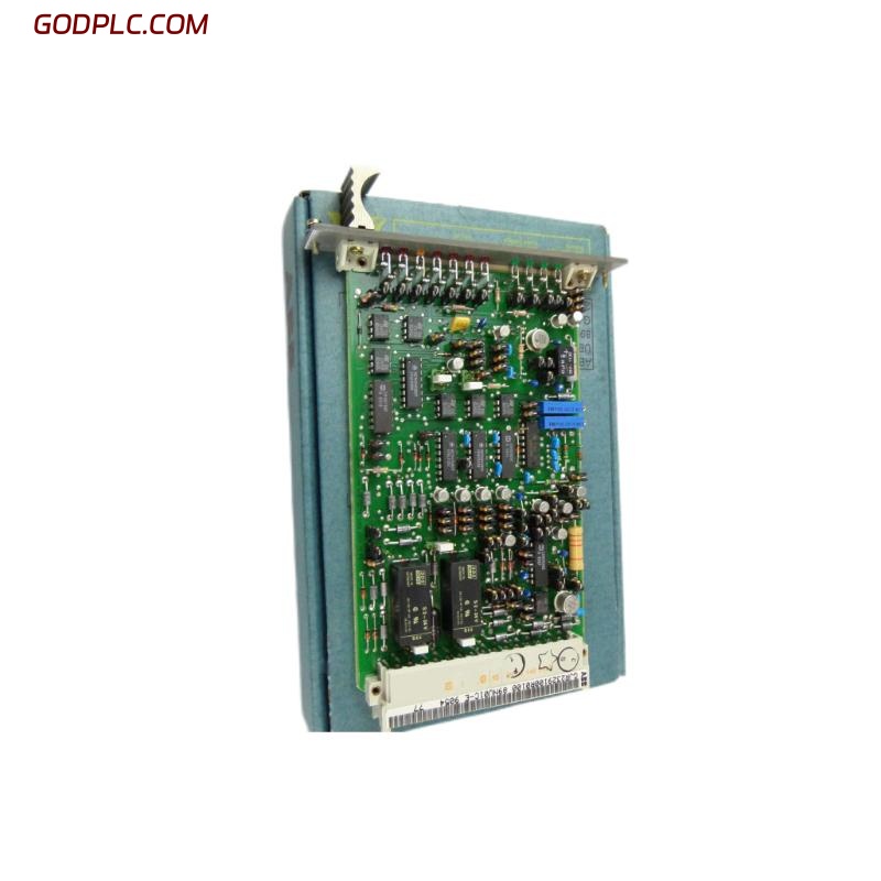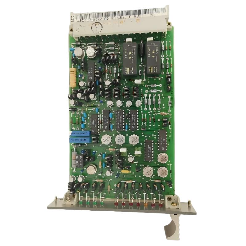
ABB 70VV01a HESG447043R1 Circuit Protection Module Overview
The ABB 70VV01a HESG447043R1 Circuit Protection Module should be installed only after the existing control-system wiring, module position, grounding arrangement, and electrical conditions have been verified. For an engineer working on an older ABB control installation, the most important part of the Installation Guide is not simply mounting the module; it is confirming that the replacement module is connected to the same electrical environment as the original hardware.
The 70VV01a should therefore be treated as part of the complete control-system configuration rather than as an isolated PCB. Before Setup or Commissioning, verify the identification label, reference number, cabinet location, associated terminals, and cable routing.
ABB 70VV01a Circuit Protection Module Installation Preparation
Begin with a controlled shutdown and establish the electrical condition of the cabinet. Do not rely only on an HMI indication that the system is stopped. Field power should be isolated according to the plant’s approved maintenance procedure.
ABB 70VV01a Installation Inspection Points
- Confirm the module identification as 70VV01a and HESG447043R1.
- Record the original module position before removal.
- Inspect terminal blocks and mating connectors for oxidation or mechanical damage.
- Check cabinet grounding and bonding connections.
- Inspect nearby wiring for loose conductors, damaged insulation, or excessive cable stress.
- Keep the replacement module protected from electrostatic discharge during handling.
In field work, a significant amount of troubleshooting can be avoided by recording the original wiring before replacing a protection-related module. Photographs, terminal numbers, cable tags, and cabinet position should be documented before disconnection.
ABB 70VV01a HESG447043R1 Wiring and Connection Checks
Correct wiring is the foundation of a reliable ABB 70VV01a Setup. A module can appear mechanically correct while still producing abnormal system behavior because of a loose terminal, incorrect cable position, poor grounding, or an unexpected potential difference.
ABB 70VV01a Wiring Verification Method
- Compare every conductor with the approved cabinet drawing.
- Verify terminal numbering rather than relying only on cable color.
- Check continuity where the maintenance procedure permits it.
- Inspect shield and grounding arrangements.
- Confirm that no conductor is trapped under an adjacent terminal.
- Check connector seating before energizing the system.
Do not use resistance measurements on an energized circuit. Where live measurements are required, use the plant’s electrical safety procedure and an appropriately rated meter.
ABB 70VV01a System Configuration and Setup Verification
After physical installation, the next task is to confirm System Configuration. The replacement 70VV01a should occupy the same intended hardware position and should be compatible with the existing control architecture. If the system includes diagnostic records or hardware identification information, compare the replacement condition with the historical configuration before returning the process to normal operation.
ABB 70VV01a Setup Checklist
- Confirm cabinet location and module identity.
- Verify associated input and output circuits.
- Check system diagnostic status before process startup.
- Review recent alarm history if available.
- Confirm that no unrelated wiring changes were made during replacement.
CHECK MODULE_ID
CHECK CABINET_POSITION
CHECK TERMINAL_WIRING
CHECK GROUNDING
CHECK SYSTEM_DIAGNOSTICS
CHECK ALARM_HISTORY
ABB 70VV01a Commissioning and Functional Validation
Commissioning should be performed progressively. First verify the module under a controlled energized condition, then confirm the associated circuit behavior, and only afterward return the complete process to normal automatic operation.
ABB 70VV01a Commissioning Sequence
- Restore power according to the approved startup procedure.
- Observe system diagnostics immediately after energization.
- Check for unexpected alarms or protection indications.
- Verify the associated circuit under a controlled operating condition.
- Compare measured values with the approved plant baseline.
- Monitor the system during the initial operating period.
A useful field practice is to record measurements before and after replacement. For example, if a diagnostic point previously showed unstable voltage, record the initial reading, repeat the measurement after installation, and document the change rather than simply recording “module replaced.” This creates useful evidence for later Fault Diagnosis.
ABB 70VV01a Installation Guide: Practical Field Engineering Check
During commissioning work on legacy automation cabinets, engineers commonly discover that the visible module fault is not necessarily the original cause. A replacement module may restore operation temporarily while a loose terminal, deteriorated connector, grounding problem, or external circuit fault remains.
For this reason, the ABB 70VV01a Installation Guide should always include an inspection of the surrounding circuit. If a measured signal changes from an unstable value to a stable plant-approved value after correcting a connection, document that observation as part of the commissioning record. The measurement is more useful than a simple statement that the hardware “worked.”
ABB 70VV01a Commissioning Evidence to Record
- Module identification and installed position
- Terminal and cable verification status
- Pre-commissioning diagnostic condition
- Measured electrical values
- Post-commissioning diagnostic condition
- Alarm status after stabilization
ABB 70VV01a HESG447043R1 Installation FAQ
What should be checked before installing the ABB 70VV01a?
Verify the 70VV01a identification, cabinet position, wiring records, connector condition, grounding arrangement, and approved isolation condition before removing the existing hardware.
Can the ABB 70VV01a be commissioned immediately after installation?
The module should first undergo wiring verification and controlled energization. System diagnostics and associated circuit behavior should be checked before the process is returned to normal automatic operation.
Why is wiring inspection important during ABB 70VV01a Setup?
Loose terminals, incorrect conductors, damaged connectors, and grounding problems can create symptoms that appear to be hardware failures. Checking the external circuit helps separate installation problems from module faults.
What information should be recorded during ABB 70VV01a Commissioning?
Record the module identification, installation position, wiring verification, diagnostic condition, measured electrical values, alarms, and final operating status. These records make future Troubleshooting and Fault Diagnosis considerably easier.
ABB 70VV01a HESG447043R1 Installation Conclusion
The ABB 70VV01a HESG447043R1 Installation Guide is best approached as an engineering verification process rather than a simple replacement procedure. Correct identification, controlled wiring work, System Configuration checks, electrical inspection, and staged Commissioning provide the basis for reliable operation. When abnormal behavior remains after installation, the same records and measurements should be used as the starting point for ABB 70VV01a Troubleshooting and Fault Diagnosis.
General Note: Actual terminal assignments, electrical limits, protection parameters, and commissioning procedures must be verified against the applicable ABB documentation and the specific plant drawings before field work. Never use assumed terminal data for live industrial equipment.