
ABB 70EA02A-ES Input Module Installation Guide Overview
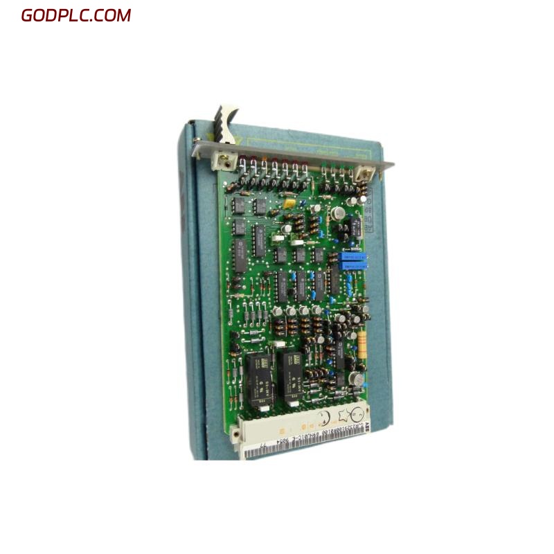
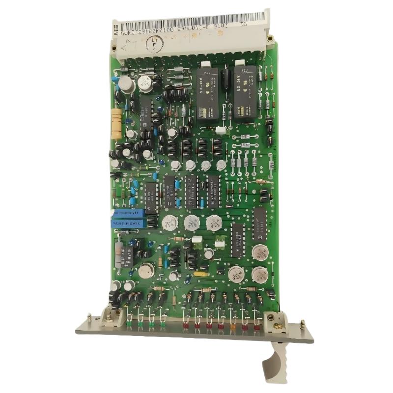
The ABB 70EA02A-ES HE666775-318/79 is an analog input module used in ABB Procontrol P13/P14 control systems, with its primary application being the acquisition of 4–20 mA signals from two-wire field transmitters. The most important commissioning point is not simply inserting the card into the rack: the field loop, module position, system configuration, and transmitter current must all agree before the input value can be trusted.
ABB 70EA02A-ES Module Role in System Configuration
Before installation, confirm that the replacement card belongs to the intended Procontrol rack and that its hardware identification agrees with the existing engineering documentation. The HE666775-318/79 identification is associated with the 70EA02A-ES input module, while related Procontrol hardware can include the rack power supply, bus interface, and controller modules.
- Verify the 70EA02A-ES module identification against the cabinet drawing.
- Confirm the assigned rack and I/O position.
- Check the channel allocation in the System Configuration.
- Identify whether each field device is a 4–20 mA two-wire transmitter.
- Compare the field tag, channel number, and DCS database before energizing the loop.
ABB 70EA02A-ES Installation Preparation and Wiring Checks
Installation should begin with the field wiring rather than the software screen. A transmitter loop that is incorrectly terminated can produce a believable but incorrect process value, making configuration errors harder to detect.
- Inspect the module connector and rack slot for contamination or mechanical damage.
- Check field cable continuity from the transmitter to the cabinet.
- Verify shield termination according to the plant grounding design.
- Confirm transmitter polarity and loop wiring before applying power.
- Record the existing channel assignment before replacing an installed card.
For a standard 4–20 mA loop, the technician should be able to identify a stable current corresponding to the transmitter process condition. A nominal 12 mA signal, for example, represents the midpoint of a standard 4–20 mA measurement range when the transmitter is configured for a linear 0–100% process span.
ABB 70EA02A-ES Input Module Wiring and Signal Verification
The 70EA02A-ES is commonly applied to two-wire transmitter signals. Because loop power and signal measurement are closely related, polarity and field-loop resistance should be checked before troubleshooting the DCS value.
- Pressure transmitter: verify the current loop and transmitter supply path.
- Flow transmitter: verify shield continuity and separation from high-power cables.
- Temperature transmitter: confirm that the transmitter output range matches the configured engineering range.
- Level transmitter: verify that the displayed value follows the expected 4–20 mA relationship.
Do not use the DCS engineering value alone to validate wiring. Measure the loop current with appropriate test equipment and compare the measured signal with the value displayed by the control system.
ABB 70EA02A-ES Setup and Commissioning Procedure
Commissioning is most reliable when performed from the field instrument toward the controller. First establish a valid electrical signal, then confirm channel recognition, and only afterward validate scaling and process logic.
- Confirm the correct module and rack position.
- Inspect the card and connector before insertion.
- Power the rack according to the approved plant procedure.
- Check module and channel status indications.
- Apply or simulate a known 4–20 mA input.
- Compare the measured current with the DCS input value.
- Verify engineering-unit scaling in the System Configuration.
- Check alarms, interlocks, and control-loop response.
ABB 70EA02A-ES Installation Diagnostics and Signal Analysis
A useful commissioning technique is to test several known current points instead of checking only one value. For example, a technician can verify approximately 4 mA, 12 mA, and 20 mA and observe whether the DCS value changes proportionally.
FIELD LOOP TEST
4.00 mA  -> verify low-range engineering value
12.00 mA -> verify approximately 50% span
20.00 mA -> verify high-range engineering value

IF measured_current != expected_current:
    inspect transmitter and field wiring
ELSE IF field_current is correct AND DCS_value is wrong:
    inspect channel configuration and input path
ELSE:
    continue system-level validation
ABB 70EA02A-ES Field Commissioning Validation
In practical commissioning work, the quickest way to separate an instrument problem from an input-module problem is to compare three points: the transmitter output, the cabinet-side loop current, and the DCS value. If the transmitter produces a stable signal but the cabinet measurement is unstable, the investigation should move toward field wiring and shielding. If the cabinet current is stable but the DCS value is incorrect, configuration or the input channel becomes the primary investigation area.
ABB 70EA02A-ES Installation and Commissioning FAQ
Can ABB 70EA02A-ES be used for 4–20 mA two-wire transmitters?
Yes. The 70EA02A-ES is commonly identified as a four-channel analog input module for 4–20 mA two-wire transmitter applications in ABB Procontrol systems. The exact wiring should always be checked against the plant drawings for the installed hardware revision.
What should be checked before installing the ABB 70EA02A-ES?
Verify the complete module identification, rack position, channel allocation, field wiring, transmitter type, and System Configuration before commissioning.
How can a 70EA02A-ES channel be validated during commissioning?
Measure a known loop current at the cabinet and compare it with the value received by the DCS. Testing more than one current point provides a better indication of scaling and signal-linearity problems.
Why should field current be measured instead of relying only on the DCS display?
A DCS display can be affected by scaling, configuration, signal conversion, or communication problems. Direct current measurement establishes whether the field instrument is actually producing the expected input signal.
What causes unstable analog values after installation?
Typical investigation points include poor shielding, grounding problems, damaged field cable, loose terminals, transmitter instability, and configuration errors. High-power equipment routed alongside analog cables can also increase electrical interference.
How should the System Configuration be checked?
Compare the physical rack position and channel number with the engineering database, signal tag, transmitter range, engineering units, alarm limits, and control-loop assignment.
What is a practical way to distinguish a transmitter fault from an input-module fault?
Measure the loop current independently. If the field signal is incorrect, investigate the transmitter and field circuit first. If the measured current is stable and correct but the DCS value is incorrect, continue with channel configuration and module-level Fault Diagnosis.
Can an existing Procontrol installation be commissioned without changing the control strategy?
A replacement input module should normally be validated against the existing engineering documentation and application configuration before assuming compatibility. The physical module identification, channel assignment, signal range, and control logic should all be confirmed.
ABB 70EA02A-ES Installation Guide Final Summary
The ABB 70EA02A-ES HE666775-318/79 installation process is best treated as an engineering validation task rather than a simple card replacement. Correct rack identification, reliable 4–20 mA wiring, accurate System Configuration, measured signal verification, and controlled commissioning are the key checks. When these points are verified in sequence, the input module can be evaluated independently from the transmitter, field cable, and higher-level DCS logic.