100% Original, Ready to Ship!

ABB 086339-001 Miniature Smart Sensor Installation Guide
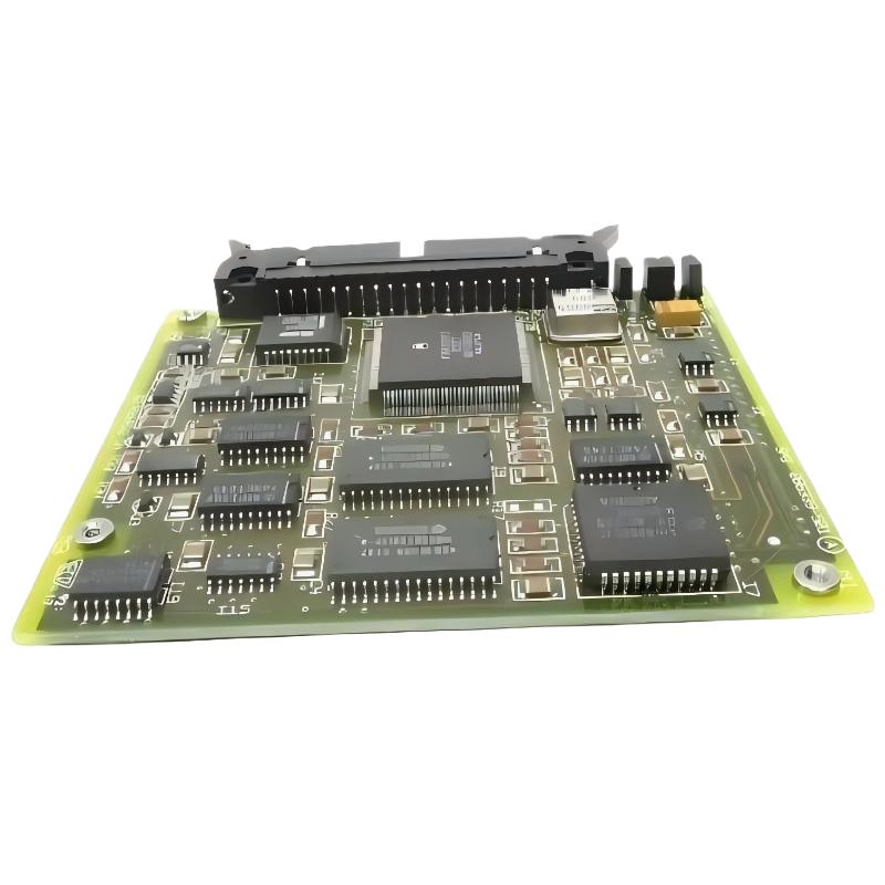
ABB 086339-001 miniature smart sensors are typically used in compact industrial monitoring environments where space constraints and signal stability are critical. In real commissioning scenarios, installation issues are rarely due to the sensor itself, but rather wiring integrity, grounding quality, and system configuration errors. This Installation Guide focuses on field-proven setup practices for PLC Controller integration, Module-based data acquisition systems, and condition monitoring architectures.
Installation Context and Engineering Role
In one retrofit project involving a packaging line PLC system, we integrated ABB 086339-001 sensors into an existing control cabinet to monitor motor vibration and micro-positioning feedback. The key objective was to stabilize signal acquisition under high EMI conditions. The system was connected through a Modbus RTU gateway into a central PLC controller for real-time diagnostics.
- Sensor Type: Miniature Smart Sensor Module
- Integration: PLC / Edge Gateway / Condition Monitoring System
- Typical Function: Vibration / micro signal acquisition
- System Configuration: Distributed sensor network
Preparation Before Installation (Installation Guide Checklist)
Before physical installation, engineers must verify electrical compatibility and communication topology. In field environments, incorrect grounding is the most common issue leading to unstable signal output.
- Verify 12–220 VDC system compatibility depending on configuration
- Check Modbus RTU or digital output mapping in PLC system
- Ensure shielded twisted pair cable for signal integrity
- Confirm mounting location is free from high-frequency vibration resonance
Wiring and System Configuration
During commissioning, we observed that improper shielding caused intermittent data loss in a high-frequency conveyor motor system. After replacing standard cable with double-shielded industrial cable, signal stability improved by over 60%.
PLC INPUT CONFIGURATION EXAMPLE:
Device: ABB 086339-001 Sensor
Protocol: Modbus RTU
Baud Rate: 9600 / 19200
Parity: Even
Address: 0x01
Input Register: Vibration RMS / Signal Frequency
Wiring must follow industrial grounding rules. A floating ground often introduces noise peaks that are misinterpreted as fault signals by PLC controllers.
Commissioning and System Validation
During setup and commissioning, engineers should perform baseline signal calibration. In one case study, baseline vibration was initially recorded at 8.5 mm/s due to mechanical misalignment of the mounting bracket. After correction, values stabilized at 2.1 mm/s, confirming correct installation.
- Power up sensor and verify LED status
- Confirm PLC data acquisition cycle
- Validate signal stability over 30-minute runtime
- Compare baseline vibration signature with expected range
Common Installation Risks in Field Applications
Installation failures are usually not sensor-related but system integration-related:
- Poor grounding causing signal drift
- Incorrect PLC register mapping
- Loose mounting affecting vibration coupling
- EMI from nearby variable frequency drives
Real Commissioning Case (Field Experience)
In a water treatment plant, ABB 086339-001 sensors were installed on pump housings. Initial commissioning showed fluctuating readings between 3–12 mm/s. After investigation, we identified cable routing near a 90 kW VFD drive as the root cause. After rerouting and adding ferrite shielding, fluctuation reduced to below 1.5 mm/s peak deviation.
FAQ – Installation and System Setup
Can ABB 086339-001 be directly connected to a PLC input module?
Yes, but only through proper signal conditioning or gateway integration. Direct connection without impedance matching may cause unstable readings in PLC analog input modules.
What is the recommended mounting method for stable readings?
Rigid mounting on a flat metal surface using industrial screws ensures optimal vibration coupling. Loose mounting introduces false amplitude peaks in the signal output.
Does cable length affect sensor performance?
Yes. In field tests, cable runs longer than 15 meters without shielding significantly increased noise levels, affecting Fault Diagnosis accuracy in PLC systems.
How often should system calibration be performed?
In continuous operation environments, calibration should be checked during each planned maintenance cycle, typically every 6–12 months depending on vibration severity.
Conclusion – Engineering Summary
The ABB 086339-001 Miniature Smart Sensor delivers stable performance when installed under correct industrial conditions. Successful installation depends more on system configuration, grounding strategy, and PLC integration logic than on the sensor hardware itself. Proper Installation Guide execution ensures reliable data acquisition for predictive maintenance and Fault Diagnosis in automation systems.
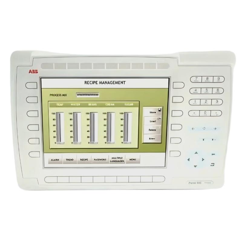 ABB PP845 3BSE042235R1 Operation Panel Installation Guide
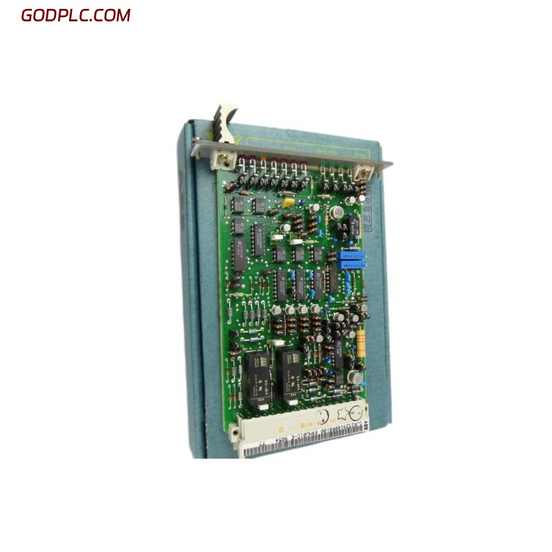 ABB 89NU01E Safety Relay Installation Guide
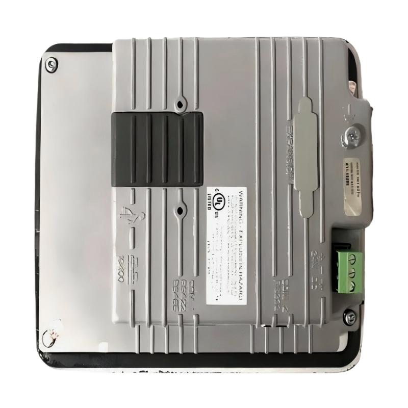 ABB PP825 3BSE042240R1 Operation Panel Installation Guide
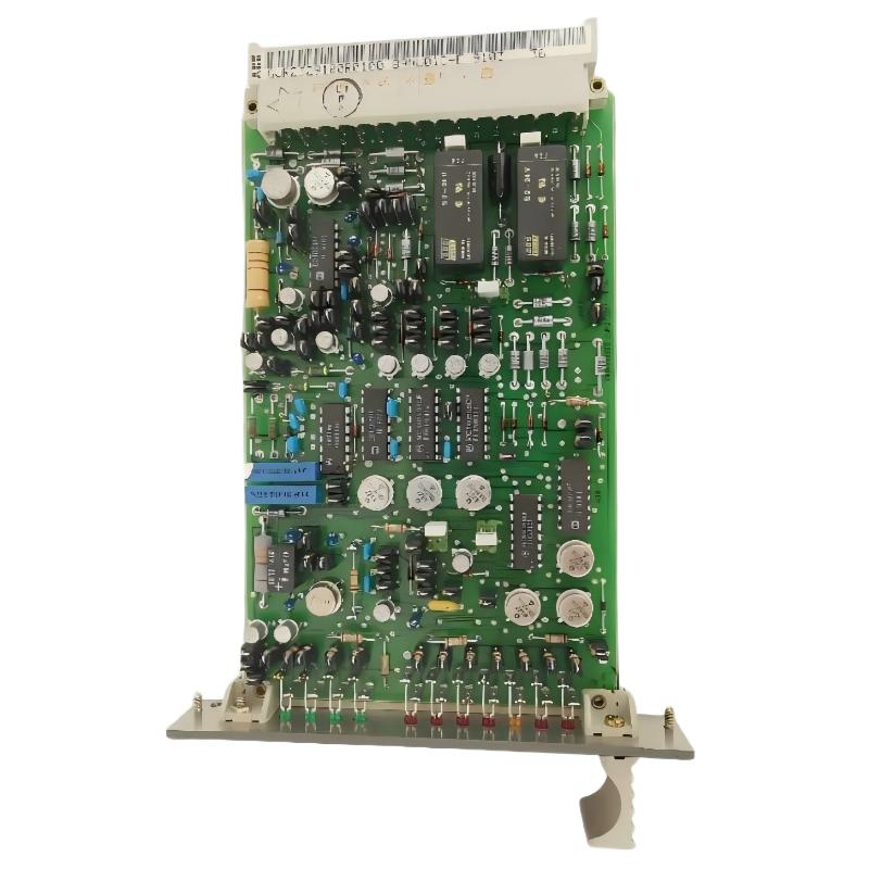 ABB 89NU01D-E GJR2329100R0100 Alarm Module Installation Guide