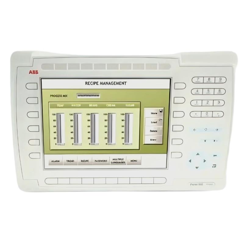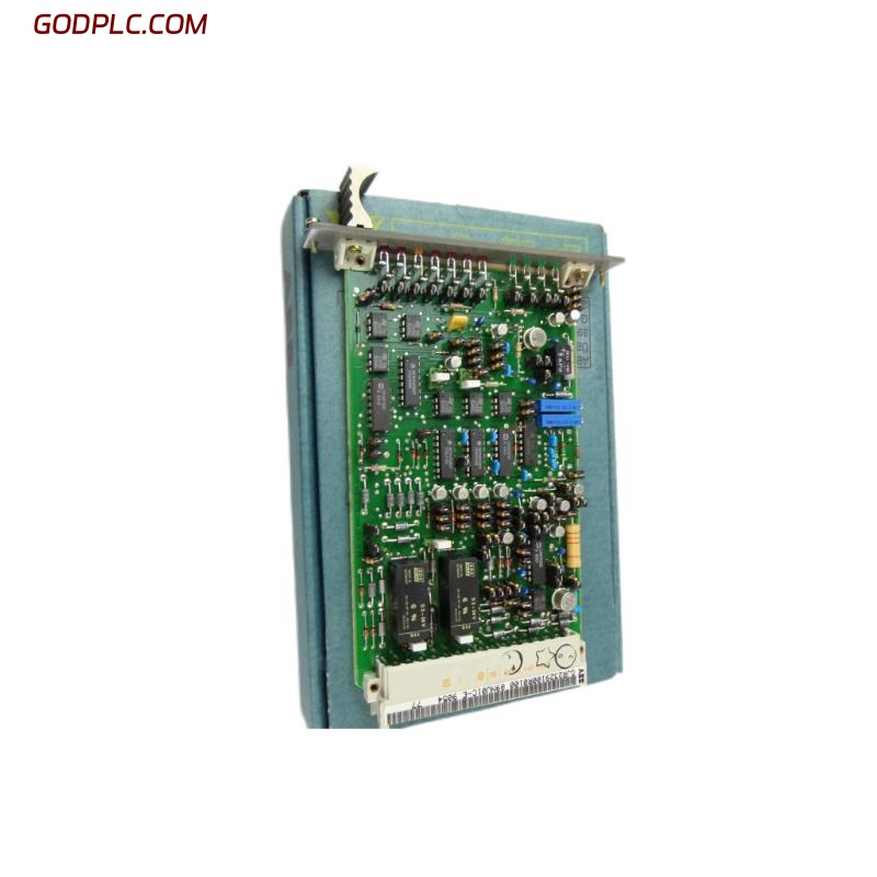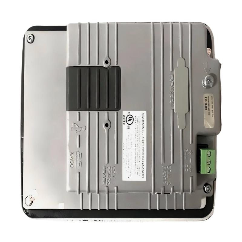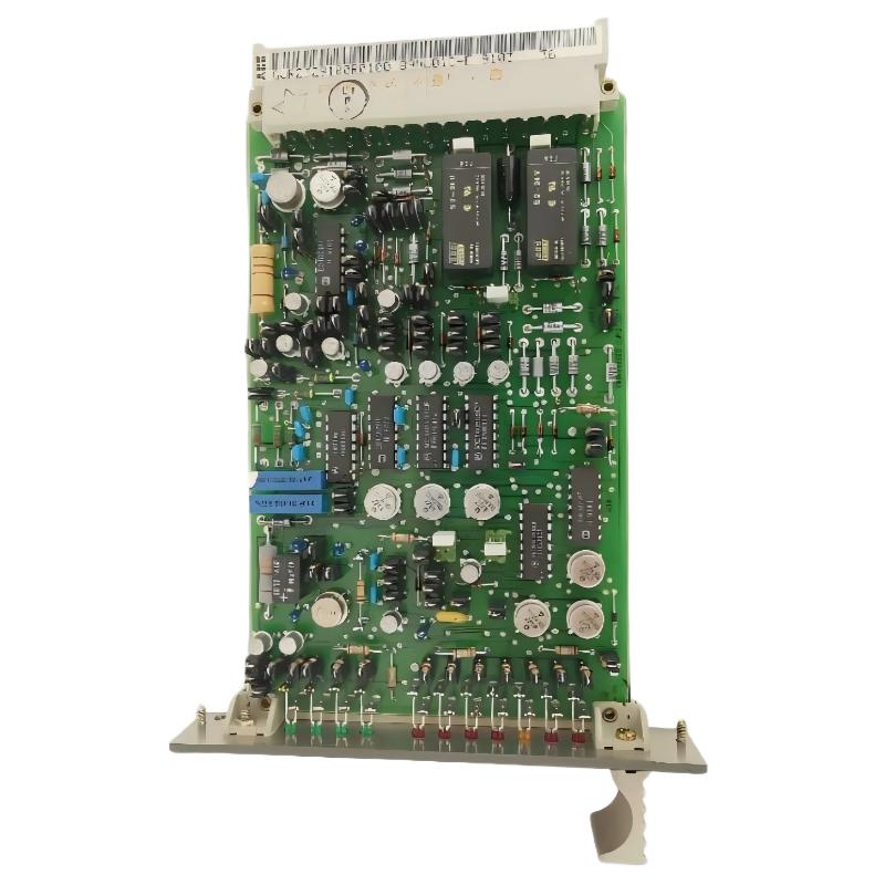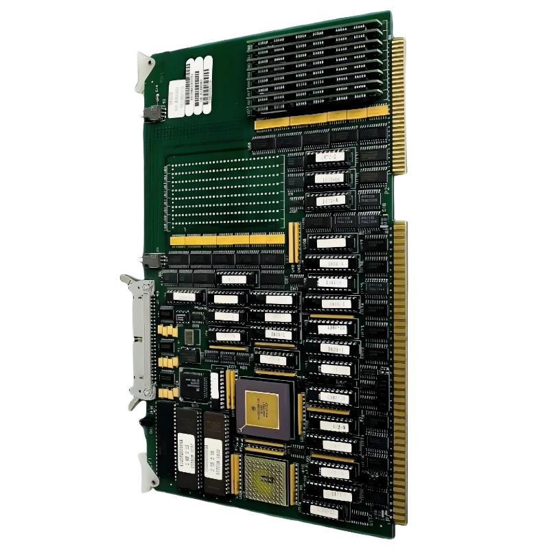
ABB 6026BZ10300G PCB Card Installation Guide Overview
ABB 6026BZ10300G installation should begin with board identification, power isolation, connector inspection, and system compatibility checks rather than immediate card replacement. The 6026BZ10300G is commonly identified in industrial automation spare-parts references as a Taylor control board associated with a 68020 CPU architecture and 8 MB memory configuration. Because this type of PCB can participate in control logic, improper handling or incorrect system configuration can create faults that appear to be software or field-signal problems.
This Installation Guide focuses on practical PCB Card replacement, Setup, Commissioning, and post-installation validation. The objective is to establish a known electrical condition before the controller is returned to service.
ABB 6026BZ10300G PCB Card Installation Preparation
Before removing the existing card, record the operating condition of the control system. In field work, this information is often more useful than the board itself when commissioning problems appear later.
- Record the existing card identification and revision markings.
- Photograph connector locations and cable routing before removal.
- Document active alarms and controller status indicators.
- Verify the replacement 6026BZ10300G matches the required hardware configuration.
- Check cabinet grounding and power-supply stability.
- Use an ESD wrist strap and an approved antistatic work surface.
- Confirm that the control process is in a safe maintenance state.
ABB 6026BZ10300G System Configuration and Compatibility Checks
The PCB should be treated as part of the complete control architecture rather than as an isolated component. Check the host controller, backplane or carrier connections, associated interface boards, memory configuration, and application-specific settings before energizing the system.
A useful engineering rule is to compare the replacement board against the failed board at three levels: physical identification, electrical interface, and application configuration. A board that fits mechanically is not automatically a correct replacement.
ABB 6026BZ10300G PCB Card Wiring and Connector Inspection
The 6026BZ10300G PCB Card should not be connected while the system is energized unless the specific equipment documentation explicitly permits hot swapping. Inspect every connector for bent contacts, oxidation, contamination, or mechanical damage.
- Isolate the relevant control power.
- Verify the absence of hazardous voltage using the site’s approved procedure.
- Disconnect external connections without pulling directly on conductors.
- Inspect connector keys and board guides.
- Install the replacement PCB evenly without forcing it into position.
- Reconnect cables according to the recorded installation reference.
- Recheck connector seating before restoring power.
ABB 6026BZ10300G PCB Card Setup and Commissioning
During Commissioning, restore power in a controlled sequence. Do not immediately place the complete process into automatic operation. First confirm that the controller reaches a stable state and that the expected communication and diagnostic indications are present.
For a replacement board, the commissioning sequence should include a cold-start observation, controller status verification, configuration comparison, and controlled functional test.
Power OFF
    |
Install 6026BZ10300G
    |
Inspect connectors and grounding
    |
Power ON
    |
Observe controller initialization
    |
Verify system configuration
    |
Check alarms and status
    |
Perform controlled functional test
ABB 6026BZ10300G PCB Card Commissioning Validation
Do not judge a successful installation only by whether the controller starts. A reliable Commissioning check should also verify stable operation under representative load conditions.
- Confirm controller initialization completes normally.
- Check that expected status indications remain stable.
- Verify associated I/O or control functions respond correctly.
- Monitor supply voltage during startup and steady-state operation.
- Check for intermittent alarms after thermal stabilization.
- Compare operating behavior with the pre-maintenance baseline.
ABB 6026BZ10300G PCB Card Installation Field Case
In one practical replacement scenario, a controller was reported to initialize correctly after a PCB replacement but developed intermittent control alarms after approximately 20 minutes. The initial assumption was a defective replacement board. During the investigation, the measured control supply was stable at approximately 24.1 VDC, while the cabinet temperature increased significantly after the equipment returned to normal operation.
The inspection then shifted from the PCB itself to the connector and cabinet environment. A connector was found to have insufficient mechanical seating, producing an intermittent connection during thermal expansion. After reseating the connector and securing the board correctly, the controller remained stable during an extended operating test.
The engineering lesson is important: when a newly installed PCB behaves normally during cold startup but fails after thermal or vibration changes, inspect mechanical interfaces before condemning the electronic board.
ABB 6026BZ10300G PCB Card Diagnostic Checks
When the host system provides diagnostic access, capture the controller state before resetting or clearing alarms. The following pseudo-command sequence can be used as a diagnostic workflow and should be adapted to the actual maintenance environment.
> STATUS
> ALARM LIST
> CONFIG CHECK
> I/O STATUS
> EVENT LOG
> RESET STATUS
These are diagnostic placeholders rather than vendor-specific commands. The important practice is to capture evidence before changing the system state.
ABB 6026BZ10300G PCB Card Installation FAQ
What should be checked before installing an ABB 6026BZ10300G PCB Card?
Verify the complete part number, board revision where applicable, connector condition, host-system compatibility, power isolation, grounding, and existing configuration records before installation.
Can the ABB 6026BZ10300G be installed while the controller is powered?
Do not assume hot swapping is permitted. Unless the specific host equipment documentation explicitly supports live replacement, isolate power before removing or installing the PCB.
Why is connector inspection important during 6026BZ10300G installation?
A partially seated connector can create intermittent faults that resemble PCB failure. Mechanical connection quality should therefore be verified before electrical troubleshooting becomes more complex.
What should be monitored during ABB 6026BZ10300G Commissioning?
Monitor controller initialization, diagnostic status, supply stability, associated I/O behavior, alarms, and system response under controlled operating conditions.
How should System Configuration be handled after PCB replacement?
Compare the replacement hardware and controller configuration with the known-good maintenance record. Do not modify parameters simply to eliminate an alarm without understanding the original cause.
What is the most useful field test after installing the PCB Card?
A controlled functional test followed by an extended observation period is more informative than a short startup test because intermittent connector, thermal, and configuration problems may not appear immediately.
ABB 6026BZ10300G PCB Card Installation General Overview
A reliable ABB 6026BZ10300G Installation Guide is ultimately about controlled replacement and evidence-based Commissioning. Correct board identification, ESD protection, connector inspection, System Configuration checks, and staged functional validation reduce the risk of introducing a second fault during maintenance. In field service, the strongest installation practice is to establish a baseline before replacement and prove the same operating conditions after the PCB Card has been commissioned.