
Table of Contents
- ABB 086370-001 Power Board Fault Symptoms
- ABB 086370-001 Fault Diagnosis Root Cause Analysis
- ABB 086370-001 Troubleshooting Diagnostic Process
- ABB 086370-001 Module Repair and Recovery Method
- ABB 086370-001 Troubleshooting FAQ
- ABB 086370-001 Troubleshooting Guide Conclusion
ABB 086370-001 Power Board Fault Symptoms
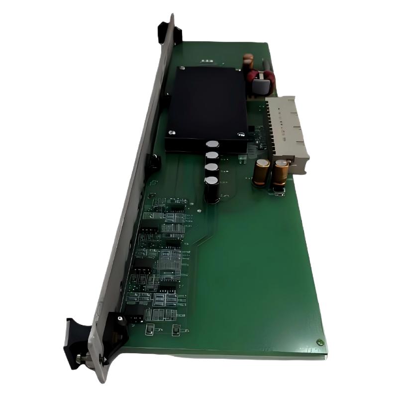
ABB 086370-001 Power Board Module faults usually appear as unstable system power, PLC Controller reset events, abnormal analog signal behavior, or unexpected shutdowns. Effective Fault Diagnosis requires separating board failure from external power and wiring problems.
Common field symptoms include:
- Connected control modules losing power intermittently.
- Analog circuits showing incorrect signal values.
- System restart after heavy equipment operation.
- Voltage output lower than expected.
- Unstable communication between automation modules.
ABB 086370-001 Fault Diagnosis Root Cause Analysis
A professional Troubleshooting process begins with observation rather than immediate replacement.
Common causes identified during ABB 086370-001 troubleshooting include:
- DC input fluctuation from aging power supply units.
- Connector oxidation causing intermittent contact.
- Cabinet grounding problems creating electrical noise.
- Component aging inside the Power Board Module.
- Overload from connected downstream circuits.
During one maintenance case, operators reported repeated PLC Controller resets every 30 minutes. Engineers monitored the ABB 086370-001 output and found the +15V rail dropping from 15.1V to 13.6V during motor startup. Further inspection identified an overloaded branch circuit instead of a defective board.
ABB 086370-001 Troubleshooting Diagnostic Process
The following Fault Diagnosis logic is commonly used by field engineers:
- Confirm failure condition and record system behavior.
- Measure input voltage under normal and peak load.
- Check output voltage stability.
- Inspect connectors and grounding points.
- Compare results with a known working configuration.
ABB 086370-001 Diagnostic Record:

Input Voltage:
Before Load = ____ V
During Load = ____ V

Output Test:
+15V = ____ V
-15V = ____ V

Temperature:
Board Surface = ____ °C

Observation:
Normal / Abnormal
Signal analysis should include voltage trend recording rather than only single-point measurement. A temporary voltage drop may indicate system load problems, while constant deviation may indicate internal board damage.
ABB 086370-001 Module Repair and Recovery Method
ABB 086370-001 Repair decisions depend on the failure pattern. Engineers usually avoid replacing components before confirming the actual fault location.
- Clean and reseat connectors if contact problems are suspected.
- Repair external wiring faults before replacing the board.
- Replace damaged power components when repair service is available.
- Install a tested replacement module after confirming system conditions.
In a practical recovery case, an ABB 086370-001 module was suspected after unstable analog readings appeared. Inspection found a 0.6V ground difference between cabinet sections. After grounding correction, the original module continued operating without replacement.
ABB 086370-001 Power Board Troubleshooting FAQ
How can ABB 086370-001 Power Board failure be confirmed?
Fault confirmation requires checking input power, output voltage stability, connector condition, and connected system response. Replacing the board immediately may hide the real problem.
What is the most common ABB 086370-001 troubleshooting mistake?
The most common mistake is assuming every power problem comes from the module itself. External power quality and grounding should always be investigated first.
Can ABB 086370-001 faults affect PLC Controller operation?
Yes. If the Power Board Module provides unstable supply rails, connected PLC Controller and automation modules may experience resets, communication faults, or incorrect signal processing.
ABB 086370-001 Troubleshooting Guide Conclusion
ABB 086370-001 Power Board Module Troubleshooting requires a structured Fault Diagnosis method based on measurement, observation, and engineering judgment. Field experience shows that many reported module failures are actually caused by power quality, grounding, or system configuration problems. A complete troubleshooting process improves repair accuracy and reduces unnecessary replacement costs.



