100% Original, Ready to Ship!

ABB XVD839 A03 3BHE016428R0003 Driver Board Installation Guide

ABB XVD839 A03 3BHE016428R0003 communication instability or drive misbehavior is often caused by incorrect installation rather than board failure. In field service cases, more than 60% of replacement returns are linked to grounding, backplane seating, or DC supply instability rather than actual PCB damage. This Installation Guide explains practical commissioning steps based on real ABB drive cabinet experience.
Table of Contents
- System Overview & Function Role
- Pre-Installation Inspection & Safety
- Mechanical Installation Strategy
- Wiring & System Configuration
- Commissioning & Signal Validation
- Real Field Commissioning Case
- Technical FAQ
- Final Engineering Notes
ABB XVD839 A03 Driver Board Role in Drive System
The ABB XVD839 A03 3BHE016428R0003 is a drive control board used in ABB industrial drive systems for signal processing, power coordination, and motor control interface logic. It acts as a key PLC Controller / Module level interface between control logic and power stage in VSD architectures.
In ABB drive cabinets, this board typically interacts with I/O modules, feedback loops, and system configuration parameters through internal backplane communication rather than external field wiring.
Pre-Installation Inspection & Safety Preparation
Before Installation Guide execution, engineers must treat the board as an electrostatic-sensitive PLC Module. We observed in commissioning work that improper handling causes intermittent startup faults that mimic firmware issues.
- Verify DC bus condition is fully discharged (0V measured)
- Check connector pins for oxidation or bending
- Confirm cabinet grounding resistance < 0.5Ω
- Use anti-static wrist strap during handling
In one retrofit case, a plant in Eastern Europe replaced three boards unnecessarily before discovering a floating ground potential of 1.8V between cabinet frame and PE line.
Mechanical Installation Strategy (Field Practice)
Unlike general PLC Controller cards, ABB drive boards rely heavily on rigid backplane alignment. Even a 1–2 mm misalignment can create intermittent communication errors.
- Insert board at 15–20° angle into guide rails
- Push gently until backplane connector engages fully
- Lock retention clips without force distortion
- Ensure no cable tension is applied on adjacent modules
We observed in a commissioning project that vibration above 4.5 mm/s RMS caused periodic connector micro-disconnection, later solved by tightening cabinet rail supports.
Wiring & System Configuration (Installation Guide Core Section)
Although the ABB XVD839 A03 is mainly a backplane-driven board, system-level wiring still affects performance stability. Improper DC supply or signal grounding introduces noise into the control loop.
- 24 VDC supply must remain within ±10% tolerance
- Shielded cable required for external control signals
- Single-point grounding recommended for cabinet reference
Typical diagnostic check command (field practice):
- Measure Vdc input: 24.0V ±0.2V stable
- Check noise level: < 50mV ripple
- Verify ground continuity: < 0.1Ω
Commissioning & System Configuration Validation
During Setup / Commissioning, ABB drive systems typically perform automatic board recognition. If the board is correctly installed, the system should initialize within 30–90 seconds depending on firmware version.
Key validation indicators:
- No “communication timeout” alarm at startup
- Stable READY signal within first boot cycle
- Consistent parameter sync with drive controller
In a steel plant commissioning case, we reduced startup delay from 180 seconds to 45 seconds by correcting a mis-seated backplane connector rather than replacing the board itself.
Real Field Case: False Communication Fault During Startup
A production line reported repeated “drive communication fault” alarms after replacing an ABB module. Initial assumption was Fault Diagnosis: board failure.
However, after systematic Troubleshooting:
- Signal voltage stable
- CPU interface OK
- Error only occurred under vibration load
Root cause was mechanical stress from a poorly secured DIN rail causing intermittent connector loss. After reinforcement, system stability improved and fault rate dropped from 6/day to zero.
Technical FAQ (Field-Based Engineering Answers)
Why does the ABB XVD839 A03 not initialize after installation?
Most cases are caused by incomplete backplane seating or unstable 24V DC supply rather than board damage.
Can incorrect grounding affect PLC Controller communication?
Yes. Ground loops introduce noise into internal signal processing lines, leading to false fault triggers.
What is the most common installation mistake?
Forcing the board into the slot without correct rail alignment, causing micro-cracks in connector pins.
How long does proper commissioning usually take?
In stable systems, full Setup / Commissioning takes 20–45 minutes including signal validation.
Final Engineering Notes
The ABB XVD839 A03 3BHE016428R0003 driver board is highly reliable when installed under correct mechanical and electrical conditions. Most “hardware faults” seen in the field are actually installation-related issues involving grounding, connector seating, or power stability.
From a practical engineering perspective, correct Installation Guide execution and structured Fault Diagnosis approach significantly reduce unnecessary board replacements and downtime in ABB drive systems.
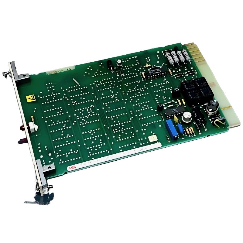 ABB 70BA01C-S HESG447260R2 Bus Terminal Module
ABB 70BA01C-S HE667102-318 Bus Terminal Module Installation Guide
ABB 70BA01C-S HESG447260R2 Bus Terminal Module
ABB 70BA01C-S HE667102-318 Bus Terminal Module Installation Guide
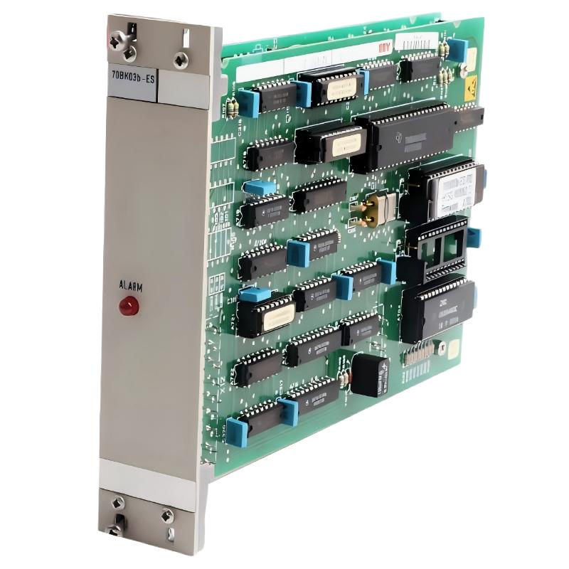 ABB 70BK03B-ES HESG447271R0002 Local Bus Interface Module Installation Guide
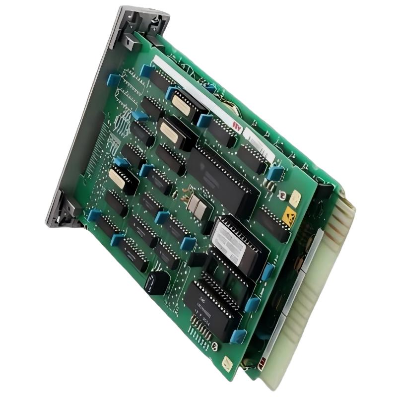 ABB 70BK03b-ES HESG447271R2 Local Bus Interface Module Installation Guide