100% Original, Ready to Ship!

ABB XZ C826 A103 3BHE036348R0103 Driver Board Troubleshooting Guide
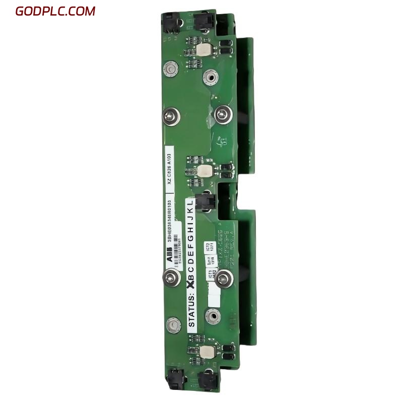
ABB XZC826A103 driver board faults typically present as intermittent inverter trips, “Gate Driver Fault”, or unstable motor speed regulation. In most real field cases, the module itself is not physically damaged; instead, the root cause is signal disruption inside the drive cabinet or degraded interface connections.
In a cement plant case study, the drive tripped randomly under medium load (60–70%). Initial suspicion was IGBT failure, but later diagnosis showed unstable trigger pulses caused by oxidation on the board connector pins.
- Unexpected inverter shutdown under load
- Communication loss with main control unit
- Irregular motor speed fluctuation
ABB XZC826A103 Common Causes of Fault Conditions
Fault Diagnosis for this driver board must consider both electrical and environmental factors. Unlike standard PLC Module systems, inverter driver boards are highly sensitive to EMI and grounding quality.
Field engineers often misinterpret symptoms as hardware failure, while the real issue is external interference or degraded power quality.
- EMI interference from nearby high-power VFD cables
- Poor grounding or floating neutral condition
- Backplane connector wear or oxidation
- Firmware mismatch between control board and inverter unit
Typical fault log example:
FAULT CODE: 5090
EVENT: GATE SIGNAL LOSS
STATUS: INTERMITTENT
ABB Driver Board Fault Diagnosis Process (Engineering Workflow)
The correct Fault Diagnosis process should always start from system-level checks before replacing hardware. Swapping the driver board without validation often leads to repeated failure.
In one offshore pump station, three boards were replaced within two weeks. The real issue was unstable auxiliary 24V DC supply dropping to 19.6V during peak load conditions.
- Verify DC supply stability (24V ±5%)
- Check grounding impedance (< 0.1Ω target)
- Inspect fiber-optic or ribbon signal integrity
- Analyze inverter fault history log
ABB XZC826A103 Repair and Recovery Actions
Repair strategy depends on symptom severity. In many cases, cleaning and reseating connectors restores normal operation without component replacement.
We observed a recovery case where motor oscillation reduced from ±15% speed variation to stable ±2% after replacing a partially oxidized connector strip.
- Clean control connectors with approved ESD-safe solution
- Re-seat driver board and lock mechanical supports
- Replace auxiliary 24V power supply if unstable
Recovery validation:
- Stable run > 30 minutes
- No fault reappearance
- Constant PWM output observed
ABB Driver Board Advanced Fault Scenarios (Real Field Experience)
Some failures only appear under thermal load. For example, intermittent gate signal loss after 40–60 minutes of operation is often linked to thermal drift in surrounding power modules rather than the board itself.
In one industrial fan system, fault frequency increased during summer operation. Thermal imaging revealed hotspot near adjacent rectifier module reaching 78°C, affecting signal stability of the driver board.
ABB XZC826A103 Troubleshooting FAQ (Field Engineer Notes)
Why does the inverter fault appear only under load?
This usually indicates voltage drop or EMI coupling that only becomes significant during high current operation.
Can a faulty driver board damage the motor?
Indirectly yes, if PWM instability persists, it may cause torque ripple and mechanical stress, but direct motor damage is rare.
Is replacing the board enough to fix the fault?
No. Without correcting grounding or supply instability, the fault will reoccur even with a new module.
What is the most reliable diagnostic method?
Combining fault log analysis with live DC bus monitoring gives the most accurate root cause identification in ABB inverter systems.
Conclusion: ABB XZC826A103 Fault Diagnosis Summary
The ABB XZC826A103 3BHE036348R0103 driver board troubleshooting process must follow a system-level engineering logic rather than simple component replacement. Most faults originate from external electrical conditions such as grounding, EMI, or unstable auxiliary power.
A structured Fault Diagnosis approach ensures faster recovery, reduces downtime, and improves long-term reliability of ABB PLC Controller-based drive systems in harsh industrial environments.
 ABB 216NG63 Auxiliary Power Module Troubleshooting Guide
 ABB 216EA62 1MRB150083R1/F Analog Input Unit Troubleshooting Guide
ABB 216EA62 1MRB150083R1/C Analog Input Unit Troubleshooting Guide
ABB 216EA62 1MRB150083R1/F Analog Input Unit Troubleshooting Guide
ABB 216EA62 1MRB150083R1/C Analog Input Unit Troubleshooting Guide
 ABB 216EA61B HESG324015R1/K Input Module Troubleshooting Guide