Table of Contents
- ABB 216EA61B Input Module Fault Symptoms
- ABB 216EA61B Fault Diagnosis Process
- Common Causes of ABB 216EA61B Input Module Fault
- ABB 216EA61B Module Recovery Method
- Real Field Troubleshooting Case
- ABB 216EA61B Troubleshooting FAQ
ABB 216EA61B Input Module Fault Symptoms
ABB 216EA61B communication and input signal faults are commonly caused by field wiring problems, configuration errors, or unstable power conditions. Engineers should analyze the complete signal path before deciding that the PLC Module has failed.
- Input channel value remains frozen
- PLC Controller displays incorrect field data
- Module alarm LED appears abnormal
- Signal changes without process variation
- System reports input communication errors
ABB 216EA61B Fault Diagnosis Process
A professional Troubleshooting approach starts from the field device and moves toward the control system. This prevents unnecessary module replacement.
- Check field sensor output.
- Measure input signal at terminal level.
- Compare actual value with PLC database value.
- Verify module configuration parameters.
- Inspect rack communication status.
Diagnostic Logic:

IF Field Signal = Normal
AND PLC Value = Incorrect
THEN Check Module Configuration

IF Field Signal = Unstable
THEN Check Cable Shielding and Grounding
Common Causes of ABB 216EA61B Input Module Fault
- EMI interference from frequency converters
- Incorrect signal range configuration
- Loose terminal connections
- Poor grounding condition
- Aging field transmitter output
ABB 216EA61B Module Recovery Method
After identifying the root cause, recovery should follow a controlled procedure instead of random replacement.
- Correct wiring mistakes
- Restore proper System Configuration
- Restart controller communication
- Verify stable input values
- Record final diagnostic results
Real Field Troubleshooting Case of ABB 216EA61B
During one plant maintenance activity, an ABB 216EA61B Input Module generated unstable measurement values. The maintenance team initially suspected an internal Module problem.
After checking the input signal, engineers found the transmitter output was correct at 20.1mA, but the PLC displayed fluctuations between 16mA and 19mA. Further inspection discovered a damaged shield connection close to a 90kW motor starter.
After cable replacement and grounding correction, the signal returned to a stable 20.0mA reading. The Fault Diagnosis process avoided unnecessary module replacement and reduced downtime.
ABB 216EA61B Input Module Troubleshooting FAQ
Why does ABB 216EA61B show unstable input values?
Unstable values are usually related to signal interference, grounding problems, damaged cables, or incorrect transmitter output.
How can engineers confirm ABB 216EA61B module failure?
Engineers should compare field signal measurements, configuration parameters, and another verified input channel before confirming hardware failure.
What is the first step in ABB 216EA61B Fault Diagnosis?
The first step is checking whether the field signal itself is correct before analyzing the PLC Controller or Module hardware.
Can configuration errors create ABB 216EA61B faults?
Yes, incorrect System Configuration parameters can cause incorrect readings even when the hardware operates normally.
General Overview of ABB 216EA61B Troubleshooting
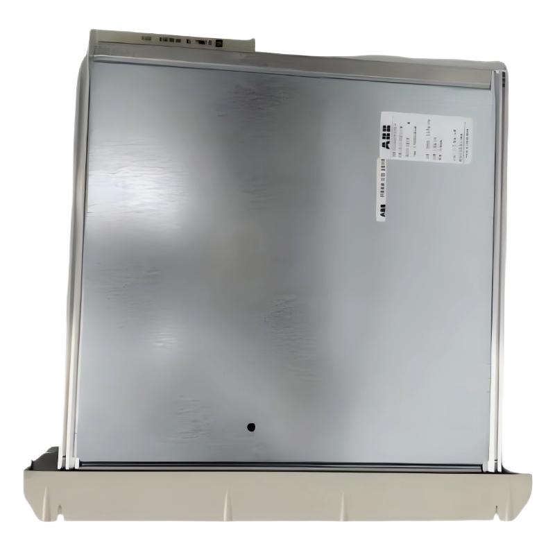
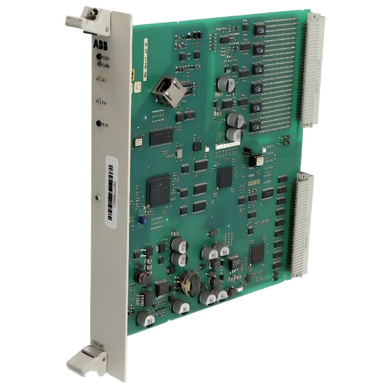
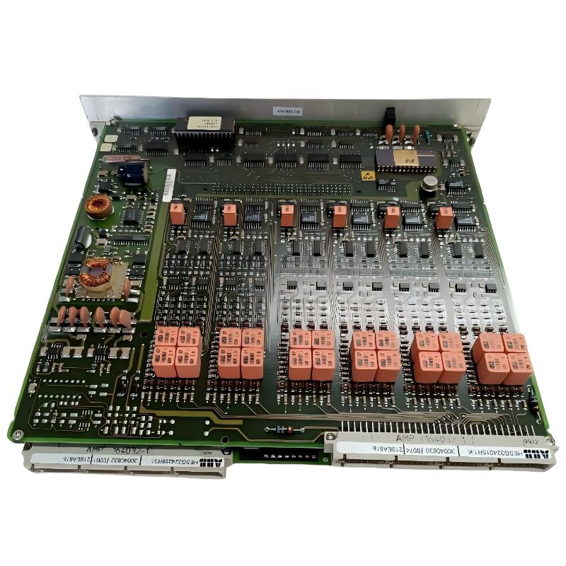
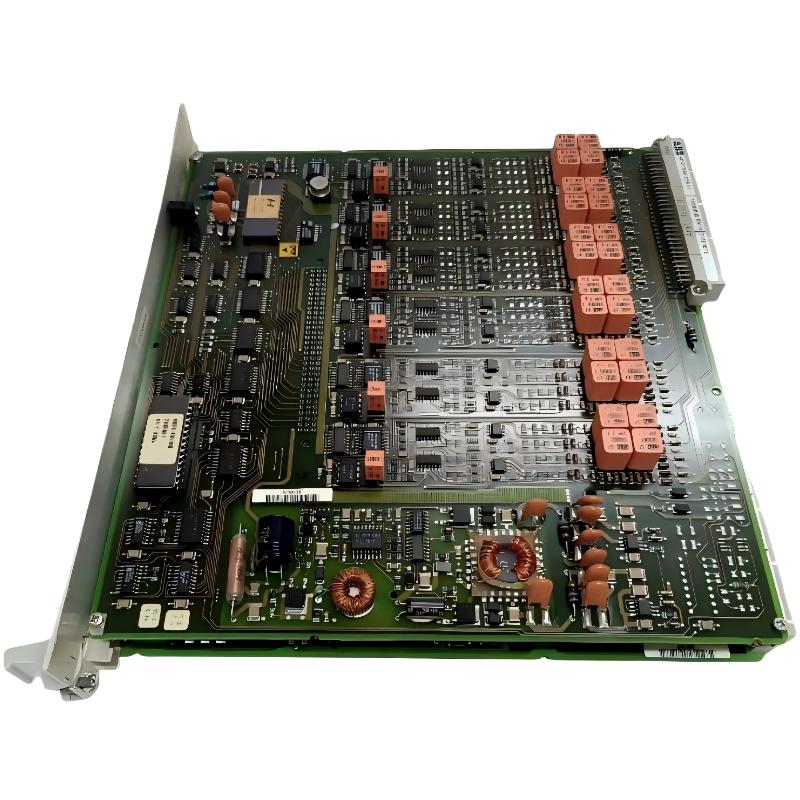
ABB 216EA61B HESG324015R1/K Input Module troubleshooting requires engineering analysis rather than simple replacement. Practical Fault Diagnosis should include signal measurement, wiring inspection, configuration verification, and field condition evaluation.