100% Original, Ready to Ship!

ABB SS110 3BSE007698R1 Voting Unit Troubleshooting Guide
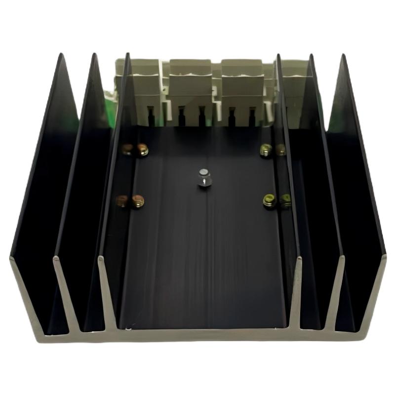
ABB SS110 3BSE007698R1 Power Voting Unit Fault Diagnosis
ABB SS110 3BSE007698R1 power voting problems commonly appear as unstable 24V DC output, loss of redundant power support, unexpected downstream equipment resets, or abnormal voltage behavior when one supply branch is disconnected. Before identifying the SS110 as defective, engineers should investigate both incoming power sources, branch protection, wiring integrity, and the connected load. The ABB SS110 is a DC 24V Voting Unit, so its Troubleshooting process must focus on the interaction between two supply inputs and the common output.
This guide explains practical Fault Diagnosis methods, electrical inspection procedures, typical failure patterns, and repair considerations for the ABB SS110 used in industrial automation and ABB Advant control systems.
Recognizing ABB SS110 Power Voting Unit Failure Symptoms
Power voting faults are not always caused by internal hardware damage. In many industrial installations, an abnormal output condition can originate from an upstream supply problem or a connection issue.
Common symptoms include:
- The common 24V DC output is below the expected operating range.
- Downstream PLC or control equipment restarts unexpectedly.
- The output becomes unstable when one supply branch is isolated.
- One incoming power source carries an abnormal load.
- Power redundancy is lost even though both upstream supplies appear operational.
- Intermittent power interruptions occur during switching or maintenance.
- Voltage readings differ significantly between the input and output measurement points.
When these symptoms appear, record the operating condition and the exact time of the event. Correlating voltage measurements with system alarms can help identify whether the issue is continuous or intermittent.
ABB SS110 Fault Investigation: Start with the Power Supply Inputs
The first stage of Troubleshooting is to establish whether both incoming DC sources are healthy. Replacing the voting unit before checking the supply branches can lead to unnecessary maintenance work.
Input A and Input B Voltage Analysis
Use a calibrated digital multimeter to measure both incoming supply voltages at approved test points. Compare the readings with the nominal 24V DC system specification and the actual permitted operating range.
| Inspection Point | What to Investigate |
|---|---|
| Input A | Voltage stability, polarity, upstream protection |
| Input B | Voltage stability, polarity, upstream protection |
| Common Output | Output voltage under normal load |
| Terminal Connections | Loose wiring, oxidation, overheating |
| Downstream Load | Excessive current demand or short circuit |
Voltage Measurement Logic
For a nominal 24V DC architecture, engineers should not assume that every measurement close to 24V indicates healthy operation. The voltage must remain within the equipment’s specified limits during normal loading and controlled supply changes.
READ INPUT_A
READ INPUT_B
READ COMMON_OUTPUT

IF INPUT_A_OUT_OF_RANGE:
    INVESTIGATE_SUPPLY_A
    CHECK_BRANCH_PROTECTION

IF INPUT_B_OUT_OF_RANGE:
    INVESTIGATE_SUPPLY_B
    CHECK_BRANCH_PROTECTION

IF BOTH_INPUTS_NORMAL AND OUTPUT_ABNORMAL:
    CHECK_TERMINALS
    CHECK_LOAD
    INVESTIGATE_SS110

RECORD_ALL_MEASUREMENTS
This is pseudocode for organizing the diagnostic sequence. It is not a native ABB SS110 command set.
Common Causes of ABB SS110 3BSE007698R1 Power Faults
Unstable Upstream 24V DC Power Supply
If one incoming power source experiences voltage fluctuations, the voting unit may receive an abnormal input condition. Inspect the upstream power supply, output terminals, circuit protection, and DC distribution wiring before investigating the SS110 itself.
Loose or Oxidized Electrical Connections
A loose terminal can create additional resistance and produce a voltage drop under load. In some cases, the voltage appears normal when the system is idle but decreases when downstream equipment draws more current.
Downstream Overload
A short circuit or excessive load current can cause the common output voltage to fall. Check the downstream distribution circuit and compare the measured load current with the approved system design.
Internal Voting Unit Damage
If both inputs are stable, the wiring is correct, and the downstream load is within its specified limits, an internal SS110 fault becomes a stronger possibility. Further investigation should follow the manufacturer’s approved testing and repair procedures.
Incorrect Replacement or System Configuration
A replacement unit with a different hardware designation or electrical specification may not be suitable for the existing system. Confirm the complete 3BSE007698R1 identification and compatibility before installation.
ABB SS110 Troubleshooting Through a Practical Fault Scenario
Consider an illustrative maintenance investigation in an industrial control cabinet. Operators report intermittent resets of downstream control equipment, although both redundant power supplies appear to be operating normally.
The maintenance engineer begins by recording the voltage at Input A, Input B, and the common output. Both incoming branches remain close to the nominal 24V DC level under the initial test condition.
However, when the downstream load increases, the common output voltage drops. This observation changes the diagnostic direction: instead of immediately condemning the SS110, the engineer inspects the terminal connections and checks the load distribution circuit.
A connection with excessive contact resistance is identified in the illustrative scenario. After the connection is corrected according to the approved electrical procedure, the engineer repeats the loaded voltage test and the controlled redundancy test.
The important engineering lesson is that a normal no-load voltage reading does not eliminate the possibility of a connection or load-related fault.
This example illustrates a diagnostic method and does not represent a verified historical ABB repair case or measured field-service result.
Advanced ABB SS110 Fault Diagnosis and Signal Analysis
When the basic electrical inspection does not identify the problem, engineers should compare measurements under different operating conditions. This helps separate an upstream supply fault from a voting unit fault.
Normal Operation Versus Single-Branch Operation
Record the following conditions during an approved maintenance test:
- Both power supply branches connected.
- Supply A isolated while supply B remains available.
- Supply B isolated while supply A remains available.
- Both branches restored to normal operation.
For each condition, record the input voltage, common output voltage, downstream current, and any related equipment alarms.
Example Diagnostic Record
| Test Condition | Measurement | Diagnostic Purpose |
|---|---|---|
| Both supplies active | Input A, Input B, output voltage | Establish normal baseline |
| Supply A isolated | Input B and output voltage | Verify remaining supply path |
| Supply B isolated | Input A and output voltage | Verify alternate supply path |
| Load operating | Output voltage and load current | Identify voltage drop under load |
Use actual recorded measurements rather than estimated values. Do not disconnect either supply branch while the connected process depends on uninterrupted power unless an approved test plan and appropriate safeguards are in place.
ABB SS110 Repair and Recovery Recommendations
Once the root cause has been identified, the repair strategy should address the actual failure point rather than simply restoring temporary operation.
When the Problem Is External to the Voting Unit
- Repair or replace defective upstream power supply equipment.
- Correct loose or damaged conductors.
- Replace unsuitable branch protection components.
- Investigate downstream overloads and short circuits.
- Correct wiring errors according to the approved drawings.
When the ABB SS110 Is Suspected of Internal Failure
If the external power sources, connections, and load conditions have been verified, the SS110 should undergo further inspection by qualified personnel.
- Inspect the housing for physical damage or overheating.
- Check connectors for damaged contacts.
- Review the voltage measurements recorded during fault isolation.
- Arrange authorized component-level assessment where appropriate.
- Replace the unit if internal failure is confirmed and field repair is not approved.
Do not attempt component replacement or bypass internal protection without an approved repair procedure. For safety-critical or redundant control power systems, an incorrectly repaired voting unit can introduce a hidden single point of failure.
ABB SS110 Replacement and Post-Repair Verification
Replacing an ABB SS110 requires attention to the original power distribution design. Before removing the existing unit, document all connections and confirm the approved isolation procedure.
- Identify and isolate both incoming DC supply branches.
- Verify the absence of voltage at the designated work points.
- Record the existing terminal connections.
- Remove the defective voting unit using the approved maintenance procedure.
- Install the compatible ABB SS110 3BSE007698R1 replacement.
- Reconnect conductors according to the verified wiring documentation.
- Inspect terminal security and electrical polarity.
- Restore power according to the system recovery procedure.
- Verify output stability under the actual operating load.
- Complete the controlled redundancy test and maintenance record.
Preventive Maintenance for ABB SS110 Voting Units
Preventive inspection can reduce unexpected power distribution failures. The maintenance interval should follow the plant’s reliability strategy and the manufacturer’s requirements.
- Periodically inspect input and output terminal conditions.
- Monitor abnormal temperature changes around electrical connections.
- Review historical DC power alarms.
- Check upstream supply stability.
- Investigate repeated downstream equipment resets.
- Record voltage measurements during scheduled maintenance.
- Verify that the redundant power architecture has not been modified without engineering approval.
ABB SS110 Power Voting Unit Troubleshooting FAQ
Why does the ABB SS110 output voltage become unstable?
Possible causes include unstable incoming 24V DC power, loose terminals, excessive downstream load, wiring resistance, or internal voting unit damage. Measure both inputs and the common output before replacing the device.
Can an ABB SS110 fault cause PLC system shutdowns?
Yes. If the common DC output supplies PLC controllers, I/O modules, or associated control equipment, an interruption can cause equipment resets or shutdowns. The actual impact depends on the power distribution architecture.
How can I determine whether the SS110 itself is defective?
First verify both incoming supplies, terminal connections, polarity, and downstream load conditions. If these are normal but the common output still behaves abnormally, investigate the voting unit using the applicable ABB service documentation.
What causes an ABB SS110 to lose redundancy?
Possible reasons include failure of one upstream supply, an open branch connection, defective protection components, wiring problems, or an internal voting unit fault. Both supply paths should be tested independently under an approved procedure.
Can the ABB SS110 be repaired instead of replaced?
Repair feasibility depends on the internal failure, component condition, and availability of an approved service procedure. For critical industrial power systems, replacement with a verified compatible unit may be preferable to an unqualified component-level repair.
What information is needed when ordering an ABB SS110 replacement?
Provide the complete model designation SS110, product number 3BSE007698R1, equipment condition, and relevant hardware identification information. Verify compatibility with the existing system before ordering.
Final Technical Assessment: ABB SS110 3BSE007698R1 Fault Troubleshooting
Reliable ABB SS110 Troubleshooting depends on understanding its role as a 24V DC voting unit within a redundant power architecture. Engineers should investigate both incoming supply branches, measure the common output under load, inspect electrical connections, and evaluate the downstream distribution circuit before concluding that the hardware has failed.
A structured Fault Diagnosis process helps distinguish external power problems from internal voting unit defects. Following verified repair procedures, documenting electrical measurements, and performing controlled post-repair commissioning are essential for restoring dependable operation in ABB Advant industrial automation systems.
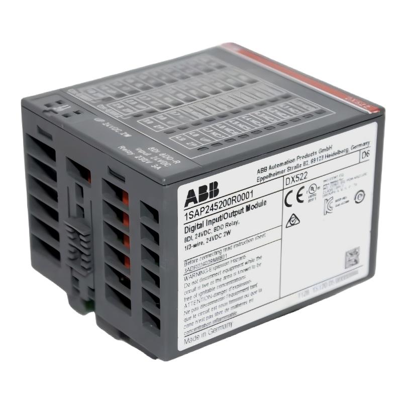 ABB DX522 1SAP245200R0001 Digital I/O Module Troubleshooting Guide
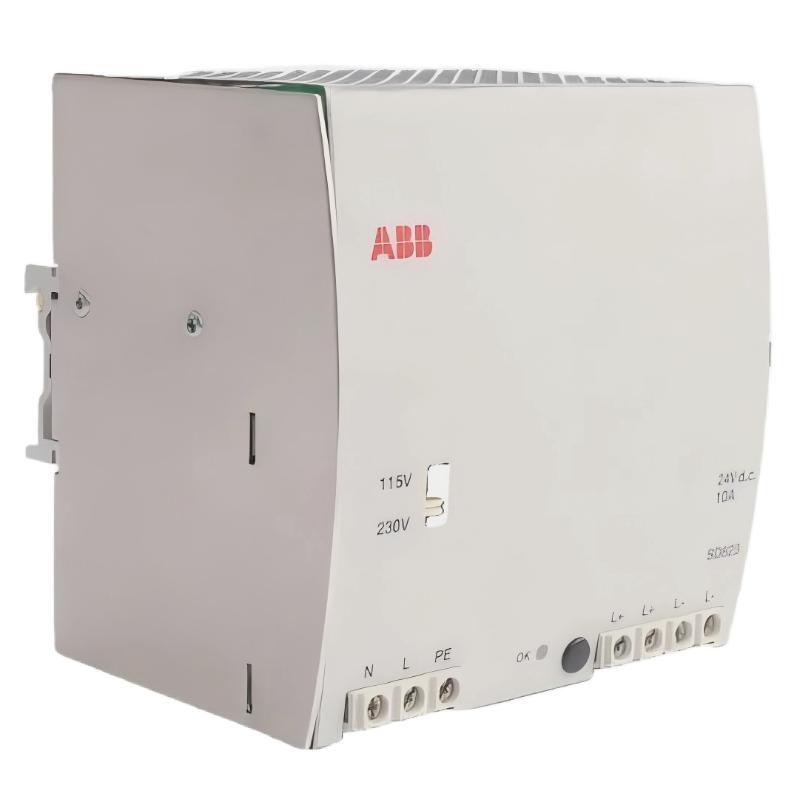 ABB SD823 3BSC610039R1 Power Supply Troubleshooting Guide
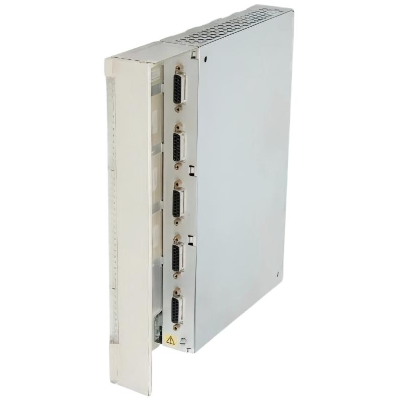 ABB DI685 3BDS005833R1 Digital Input Module Troubleshooting Guide
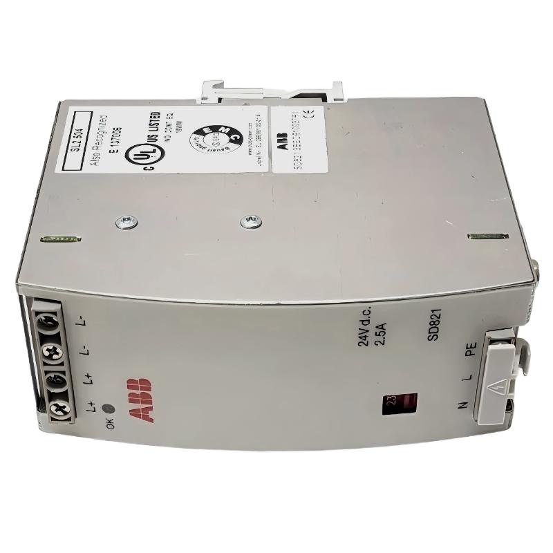 ABB SD821 3BSC610037R1 Power Supply Troubleshooting Guide