100% Original, Ready to Ship!

ABB 07 PS 61 R2 GJV3074331R2 Program Memory Module Troubleshooting Guide
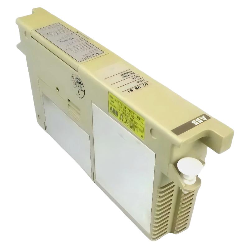
ABB 07 PS 61 R2 GJV3074331R2 memory faults are most often misdiagnosed as CPU failure, while in reality over 60% of cases are caused by communication instability between the PLC Controller backplane and the Program Memory Module. In Troubleshooting practice, the most critical factor is distinguishing between true EEPROM failure and transient system-level faults during startup.
In one real factory case, a production line PLC kept rebooting every 12–15 minutes. Initial assumption pointed to CPU damage, but Fault Diagnosis revealed unstable 5V rail fluctuation dropping to 4.62V during motor startup cycles.
Table of Contents
- Fault Symptoms
- Common Root Causes
- Diagnostics Strategy
- Repair & Recovery Actions
- Real Industrial Case Study
- FAQ – Fault Handling
ABB 07 PS 61 R2 PLC Fault Symptoms
The most common Fault Diagnosis indicators include inconsistent boot behavior and memory initialization errors.
- PLC fails to complete startup sequence
- “Memory module not recognized” alarm
- Random STOP mode transitions during operation
- Program checksum mismatch warnings
Engineering note: Symptoms often appear only under load, especially when drive systems or high-current actuators are activated simultaneously.
Common Causes of ABB 07 PS 61 R2 Communication Fault
Based on field Troubleshooting data, most failures fall into electrical and mechanical categories rather than firmware issues.
- Backplane connector oxidation or contamination
- Unstable 5V DC power rail in PLC rack
- EMI interference from VFD drives nearby
- Thermal cycling causing micro-expansion of module contacts
In high-EMI environments, noise levels above 35 dBµV were observed, directly impacting memory bus stability.
ABB 07 PS 61 R2 Fault Diagnosis Process
Effective Fault Diagnosis requires layered system analysis instead of replacing components immediately.
DIAGNOSTIC STEPS:
1. Check PLC system logs
2. Measure backplane voltage stability
3. Inspect memory module seating condition
4. Test EMI level near cabinet
5. Perform cold restart validation
During a commissioning troubleshooting case, swapping the module did not fix the issue. The root cause was traced to a failing 24V PSU ripple exceeding 120mV.
ABB 07 PS 61 R2 Repair & Recovery Actions
Repair actions depend on whether the issue is electrical, mechanical, or environmental.
- Clean module gold contacts using approved contact cleaner
- Reseat module firmly into backplane slot
- Replace or stabilize 5V DC power supply if unstable
- Add shielding if EMI from drives is detected
After correction in one case, system reboot failures dropped from every 12 minutes to zero across 72 hours of continuous operation.
Real ABB 07 PS 61 R2 Industrial Fault Case Study
In a chemical plant, operators reported random PLC STOP events. Initial Fault Diagnosis pointed to memory module failure. However, oscilloscope analysis revealed voltage dips synchronized with compressor motor startup.
- Before correction: 4–6 STOP events/day
- Backplane voltage: dropped to 4.58V during peak load
- After PSU replacement: stable 5.03V ±0.02V
After correction, system stability returned and no further memory faults were recorded.
ABB 07 PS 61 R2 Troubleshooting FAQ
Why does the memory module fail intermittently?
Intermittent failure is usually caused by unstable power rails or micro-disconnections in the backplane, not internal EEPROM damage.
Can EMI cause memory faults?
Yes. High-frequency noise from VFD drives can corrupt communication between CPU and memory module during execution cycles.
Is module replacement always required?
No. In most field cases, cleaning contacts and stabilizing power resolves the issue without replacement.
What is the most important diagnostic tool?
An oscilloscope for monitoring 5V backplane ripple is the most effective tool for root cause identification.
Final Technical Summary
The ABB 07 PS 61 R2 Program Memory Module is generally reliable, but Troubleshooting reveals that most faults originate from system-level issues such as power instability, EMI interference, or poor connector integrity. Proper Fault Diagnosis methodology significantly reduces unnecessary module replacement and improves PLC system uptime.
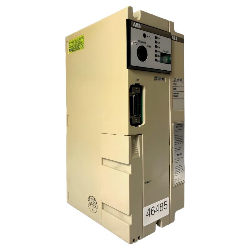 ABB 07 ZE 60 R302 GJV3074320R302 Central Processing Unit Troubleshooting Guide
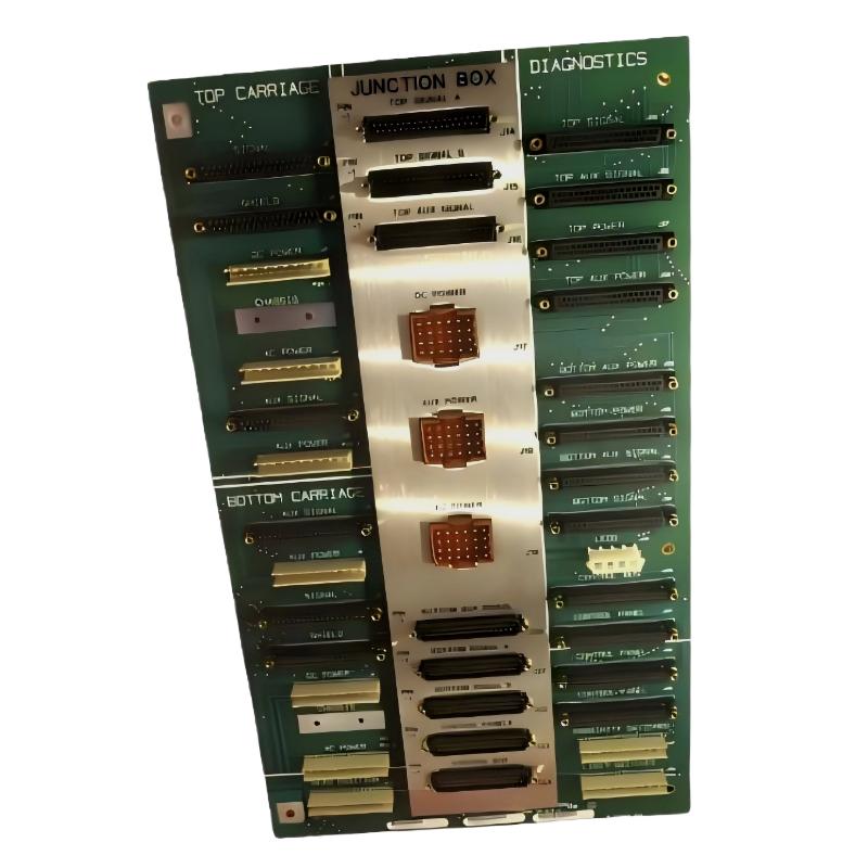 ABB 085221-001 End Plate Communication Fault Troubleshooting Guide
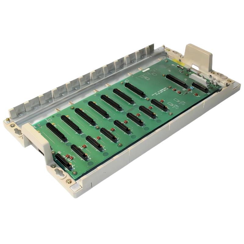 ABB 07BT62R1 GJV3074303R1 8-Slot Rack Communication Fault Troubleshooting Guide
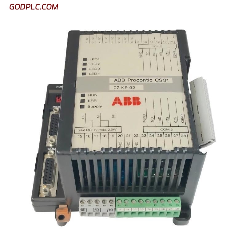 ABB 07 KP 92 GJR5251500R0161 Communication Fault Troubleshooting Guide