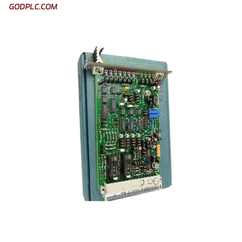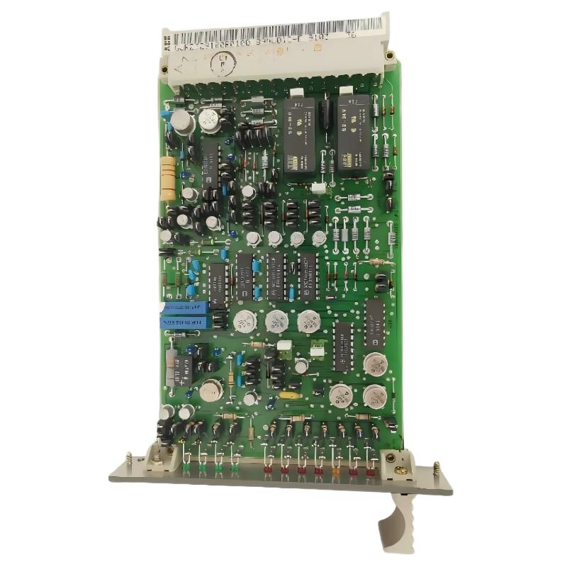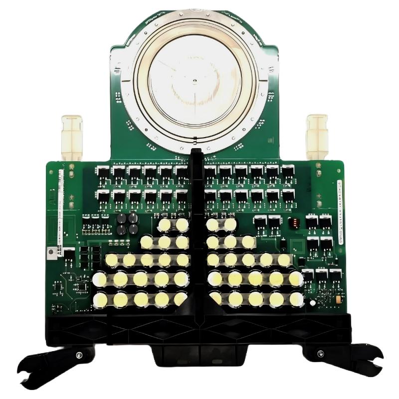
ABB 5SHX2645L0004 is identified in ABB product documentation as an IGCT RC power component with product ID 3BHL000389P0104. Before installation, the technician should verify the exact nameplate, ordering code, mechanical position, gate-unit arrangement, and converter configuration because closely related ABB IGCT variants are not automatically interchangeable.
ABB 5SHX2645L0004 IGCT Module Identification
The first task in an ABB 5SHX2645L0004 Installation Guide is not connecting cables. It is confirming the hardware identity. ABB documentation associates the type designation 5SHX2645L0004 with the IGCT RC product description, while the product documentation identifies the corresponding product ID as 3BHL000389P0104.
- Check the complete ABB type designation on the component.
- Record the product ID and serial information before removing the existing device.
- Compare the replacement with the converter’s approved spare-parts list.
- Do not select a replacement solely because another IGCT has a similar voltage or current class.
- Confirm the associated gate-drive and mechanical assembly before energization.
One important ordering-control issue is worth highlighting: some aftermarket listings describe this part with an R0104 suffix, while ABB product documentation available for the same 5SHX2645L0004 type designation identifies 3BHL000389P0104. For an actual replacement, the nameplate and the converter documentation should take priority over a supplier’s shortened description.
ABB 5SHX2645L0004 Installation Preparation
An IGCT power module is installed in a high-energy converter environment, so preparation is primarily about eliminating mechanical, electrical, and thermal uncertainty. The converter must be isolated according to the site’s electrical safety procedure, and the DC-link discharge condition must be independently verified before the enclosure is opened.
ABB 5SHX2645L0004 Safety and Inspection Checks
- Apply the plant’s approved lockout and isolation procedure.
- Verify absence of hazardous voltage using the site’s approved test equipment.
- Inspect the mounting surfaces for contamination, burrs, oxidation, or mechanical damage.
- Check the cooling arrangement and airflow path before installing the replacement.
- Inspect associated gate-drive connections for loose terminals or damaged insulation.
Do not treat the IGCT as an ordinary plug-in PLC Module. Its electrical and mechanical interfaces are part of the converter’s power circuit, and an apparently minor mounting problem can create abnormal thermal or electrical stress during the first load cycle.
ABB 5SHX2645L0004 IGCT Module Mounting
The mounting operation should follow the converter manufacturer’s mechanical procedure rather than an assumed generic semiconductor installation method. Contact pressure, alignment, cooling interface condition, and connection sequence are especially important in high-power equipment.
- Clean and inspect the approved mounting surfaces.
- Position the ABB 5SHX2645L0004 without forcing the device into alignment.
- Confirm that the module sits evenly within the mechanical assembly.
- Install the prescribed clamping or fastening hardware.
- Apply the specified tightening procedure and torque from the applicable equipment documentation.
- Reconnect the gate-drive interface and verify connector seating.
- Recheck mechanical clearance before closing the converter compartment.
Field technicians generally get better commissioning results when the mechanical inspection is documented before power is restored. A simple photograph of the installed position and recorded torque values can make later Troubleshooting considerably faster.
ABB 5SHX2645L0004 Electrical Installation
The electrical installation must be treated as part of the complete converter circuit. The IGCT itself cannot be evaluated independently from its gate-control circuit, bus connections, cooling system, protection circuitry, and surrounding power components.
ABB 5SHX2645L0004 Connection Inspection
- Verify power-terminal condition and mechanical tightness.
- Inspect insulation around adjacent conductors.
- Check gate-unit connectors for correct orientation and secure engagement.
- Confirm that no conductive debris remains inside the converter compartment.
- Compare the installed arrangement with the original documented configuration.
Do not energize the converter merely because continuity measurements appear normal. A static resistance check does not prove correct dynamic IGCT operation.
ABB 5SHX2645L0004 Setup and Commissioning
The ABB 5SHX2645L0004 Setup and Commissioning process should progress from low-risk checks toward controlled energization. The objective is to detect installation errors before the power stage is exposed to full operating stress.
ABB 5SHX2645L0004 Pre-Energization Review
- Confirm all covers, barriers, and interlocks are restored.
- Verify cooling equipment is available before power-stage operation.
- Check converter control configuration against the approved system configuration.
- Review gate-drive status and converter protection indications.
- Confirm that no active hardware fault remains in the control system.
Check converter status
Check gate-drive status
Check cooling permissive
Check DC-link protection
Check phase balance
Enable converter only after all permissives are healthy
The exact diagnostic commands depend on the converter control platform. The pseudo-command sequence above is therefore a commissioning logic example rather than an ABB software command set.
ABB 5SHX2645L0004 Commissioning Validation
After controlled energization, compare the three-phase operating behavior rather than looking only for a green status indicator. Useful observations include phase-current symmetry, DC-link behavior, gate-drive alarms, temperature rise, cooling performance, and abnormal acoustic or electrical indications.
- Record initial operating measurements before increasing load.
- Compare corresponding phase values under the same operating condition.
- Monitor temperature trend rather than relying on a single reading.
- Check for repeated gate-drive or protection events.
- Stop the commissioning sequence if an abnormal current, temperature, or protection response appears.
For EEAT-oriented maintenance documentation, the useful record is not simply “commissioned successfully.” A better record contains the converter operating condition, measured electrical values, temperature trend, alarm status, and time at each commissioning stage.
ABB 5SHX2645L0004 Installation FAQ
Can ABB 5SHX2645L0004 be replaced by another similar IGCT?
No replacement should be approved from appearance or nominal voltage alone. The exact type designation, product ID, converter application, gate-drive arrangement, mechanical assembly, and system configuration should all be checked.
Why should the gate-drive circuit be inspected during IGCT installation?
The IGCT power device operates as part of a controlled switching system. A damaged connector, incorrect interface, or gate-drive fault can prevent correct switching even when the power semiconductor itself is healthy.
Should the ABB 5SHX2645L0004 be tested at full load immediately?
No. Controlled commissioning is preferable. Start with the approved low-risk operating condition, verify protection and cooling behavior, and increase load only when the initial measurements are consistent with the equipment’s commissioning procedure.
What information should be recorded after installation?
Record the complete type designation, product identification, installation date, converter position, inspection results, relevant torque records, gate-drive status, initial electrical measurements, temperature observations, alarms, and commissioning load condition.
ABB 5SHX2645L0004 Installation Summary
A reliable ABB 5SHX2645L0004 Installation Guide should be treated as a converter-level engineering procedure rather than a simple component replacement checklist. Correct identification, mechanical installation, gate-drive inspection, cooling verification, controlled Setup, and measured Commissioning are the key stages. For long-term reliability, every commissioning measurement should be retained as a baseline for future Troubleshooting and Fault Diagnosis.