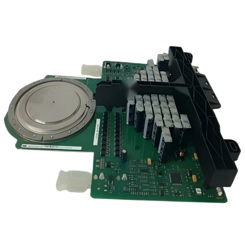
ABB 5SHX2645L0002 Installation Guide for High-Power Thyristor Switching Module
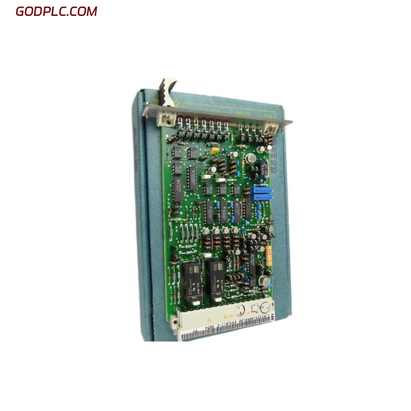
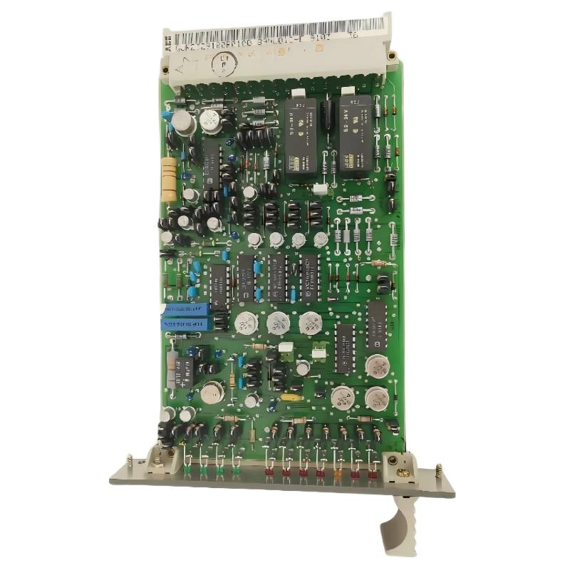
The ABB 5SHX2645L0002 high-power thyristor switching module should be installed as part of a properly engineered power-conversion assembly, with particular attention to mechanical mounting, gate-drive connections, cooling, insulation, and protection circuits. The 5SHX2645L0002 is associated with ABB part number 3BHB012961R0002 and belongs to the high-power IGCT/thyristor switching technology used in industrial power-electronic equipment.
This Installation Guide focuses on the practical engineering checks that matter before Setup and Commissioning. Unlike a conventional PLC Controller or low-power Module, a high-power semiconductor switching device cannot be commissioned safely by checking only the control signal. The complete power path, gate-drive interface, cooling arrangement, protection circuit, and System Configuration must be verified together.
ABB 5SHX2645L0002 Installation Preparation and System Configuration
Before mounting the module, confirm the exact hardware identification against the equipment documentation. The model 5SHX2645L0002 and associated part number 3BHB012961R0002 should agree with the approved system configuration.
- Confirm the module type and identification label.
- Check that the replacement or new module matches the electrical design.
- Inspect semiconductor terminals and insulating surfaces for contamination or mechanical damage.
- Verify the gate-drive interface and associated optical or electrical connections.
- Confirm that the cooling arrangement is clean and mechanically secure.
- Inspect snubber, protection, and auxiliary connections before energization.
- Check that upstream protection is correctly coordinated with the power-conversion design.
Field experience shows that many commissioning problems attributed to a thyristor module are actually caused by incorrect interfaces around the module. For this reason, installation should be treated as a complete power-stage verification rather than simply replacing a semiconductor component.
ABB 5SHX2645L0002 Mechanical Installation and Cooling Checks
Mechanical installation directly affects semiconductor reliability. The module must be mounted according to the equipment manufacturer’s mechanical and thermal requirements. Uneven mounting pressure, contaminated interfaces, or poor thermal contact can create localized heating even when the electrical circuit initially appears normal.
- Clean the mounting surface without damaging insulation or semiconductor interfaces.
- Position the module according to the approved assembly drawing.
- Verify that mounting hardware is correctly aligned.
- Apply the specified thermal interface arrangement where required by the equipment design.
- Tighten mounting hardware using the approved torque procedure.
- Check that cooling airflow or liquid-cooling paths are unobstructed.
Do not substitute an arbitrary thermal compound, mounting pressure, or torque value. Those values depend on the actual mechanical construction of the power assembly and should come from the applicable ABB documentation for the installation.
ABB 5SHX2645L0002 Wiring and Gate-Drive Installation
The power terminals and gate-drive interface must be treated separately during installation. The high-current path should be kept physically separated from sensitive control and feedback wiring wherever the equipment design permits.
- Verify the main power-terminal identification before connecting conductors.
- Confirm correct polarity and phase relationships from the approved circuit diagram.
- Route gate-drive wiring according to the original equipment layout.
- Keep high-current conductors away from low-level control wiring where practical.
- Check connector seating and locking mechanisms.
- Inspect fiber-optic interfaces for contamination, bending, or damaged connectors when optical triggering or feedback is used.
- Confirm protective earth and shielding arrangements before energization.
Do not use a PLC output directly as a substitute for the dedicated gate-drive interface. The PLC Controller may provide a supervisory command, but the semiconductor switching device requires the correct dedicated driver and protection architecture.
ABB 5SHX2645L0002 Setup and Commissioning Verification
The first commissioning stage should be performed without immediately applying full operating power. The purpose is to prove the control chain and protection logic before stressing the semiconductor stage.
A practical commissioning sequence is:
- Verify mechanical installation and cooling.
- Confirm all control and gate-drive interfaces.
- Check insulation and continuity according to the approved maintenance procedure.
- Power the control electronics independently where the system design allows this.
- Confirm gate-drive readiness and feedback status.
- Verify interlocks and protection permissives.
- Apply controlled power under the approved commissioning procedure.
- Observe current sharing, switching response, temperature, and fault feedback.
The important engineering principle is to introduce one variable at a time. If the system trips immediately after energization, do not repeatedly reset the protection. First determine whether the trip originates from the gate-drive circuit, protection circuit, power stage, cooling system, or external load.
ABB 5SHX2645L0002 Signal and Commissioning Diagnostics
During Setup, technicians should compare command signals with actual module feedback. A control command that changes state does not prove that the semiconductor has switched correctly.
CONTROL COMMAND     = ENABLE
GATE DRIVE STATUS   = READY
PROTECTION STATUS   = HEALTHY
POWER STAGE STATUS  = NORMAL
CURRENT FEEDBACK    = WITHIN APPROVED LIMIT
TEMPERATURE         = STABLE
If the command is present but the gate-drive status remains unavailable, investigate the control interface before replacing the power module. If the gate-drive status is healthy but abnormal current appears immediately after switching, the investigation should move toward the power circuit, load, commutation path, protection network, or semiconductor itself.
ABB 5SHX2645L0002 Field Commissioning Case Analysis
In a representative field commissioning scenario, a high-power converter repeatedly entered protection during the first controlled energization. The initial assumption was a defective switching module because the trip occurred immediately after the switching command.
The engineering team did not replace the module immediately. They separated the problem into command, gate-drive, power-stage, and load sections. The control command was confirmed, while the gate-drive feedback was intermittent. Inspection then found a poorly seated interface connection near the gate-drive assembly.
After the connection was corrected and the interface was rechecked, the system completed the controlled energization sequence without the previous intermittent protection event. The lesson is important for Fault Diagnosis: a protection trip occurring at the same moment as semiconductor switching does not automatically prove semiconductor failure.
ABB 5SHX2645L0002 Installation Validation and Final Checks
Before placing the equipment into normal service, record the commissioning baseline. Useful records include control status, gate-drive feedback, protection status, operating temperature, current feedback, and any available diagnostic information.
- Record the installed module identification.
- Record the final mechanical inspection result.
- Record gate-drive and protection status.
- Record initial operating measurements.
- Confirm cooling performance.
- Confirm that no abnormal alarms remain active.
- Store the commissioning data for future Troubleshooting.
ABB 5SHX2645L0002 Installation and Commissioning FAQ
What is the ABB 5SHX2645L0002 used for?
The 5SHX2645L0002 is a high-power semiconductor switching module associated with IGCT/thyristor power-conversion technology. It is intended for engineered industrial power-electronic systems rather than direct connection to a conventional PLC output.
Is the 5SHX2645L0002 controlled directly by a PLC Controller?
Normally, the PLC or higher-level control system supervises the operating command, while a dedicated gate-drive and protection circuit interfaces with the high-power semiconductor. The exact architecture depends on the host converter.
Why is cooling important during 5SHX2645L0002 commissioning?
High-power semiconductor devices generate heat during operation. Poor thermal contact, blocked cooling paths, or an abnormal cooling system can raise semiconductor temperature and cause protection trips or long-term reliability problems.
What should be checked before applying power to the module?
Check identification, mechanical mounting, cooling, power connections, gate-drive interfaces, protection circuits, insulation requirements, interlocks, and the approved System Configuration before energization.
Can a gate-drive fault be mistaken for a module fault?
Yes. An incorrect connector, damaged optical interface, missing auxiliary supply, or gate-drive protection condition can prevent normal switching even when the semiconductor itself is healthy.
What is the most useful commissioning data to record?
Record module identification, gate-drive status, protection status, current feedback, temperature, alarms, and relevant control states. These values provide a baseline for later Troubleshooting and Fault Diagnosis.
Should the module be repeatedly reset after a protection trip?
No. Repeated resets can expose the power stage to unnecessary stress. The correct approach is to determine the protection cause first and verify the control, gate-drive, power, cooling, and load conditions.
What documentation should be used for final torque and electrical limits?
The approved ABB equipment documentation and the converter-specific assembly drawings should be used for exact torque, electrical limits, wiring, insulation, and commissioning values. Generic values should not replace application-specific requirements.
ABB 5SHX2645L0002 Installation Guide Conclusion and General Overview
The ABB 5SHX2645L0002 installation process is primarily an integrated power-stage engineering task. Reliable Setup and Commissioning depend on correct mechanical mounting, thermal management, gate-drive wiring, protection logic, and System Configuration. For field engineers, the most effective approach is to validate the complete control-to-power chain rather than treating the high-power thyristor module as an isolated component. A properly recorded commissioning baseline also makes future Troubleshooting and Fault Diagnosis significantly faster.