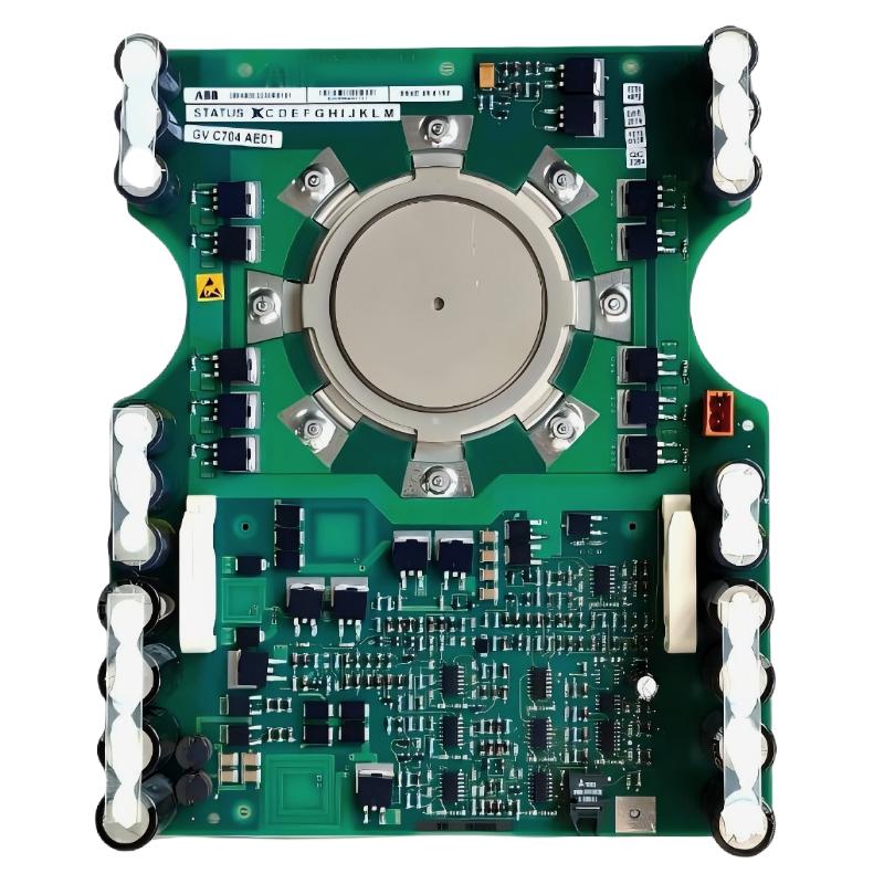
ABB 5SHX1445H0001 IGCT Module Installation Overview
ABB 5SHX1445H0001 installation should be treated as a power-stack commissioning task rather than a simple module replacement. The device is an IGCT module identified by ABB as 5SHX1445H0001, with product ID 3BHL000391P0101 and a 4.5 kV, 68 mm coated configuration. It is associated with medium-voltage drive applications, including ABB ACS 1000 systems. Correct mechanical seating, cooling, gate-drive connection, insulation condition, and system configuration must all be verified before energization.
ABB 5SHX1445H0001 Installation Preparation
Before removing an existing IGCT Module, record the original installation condition. In practical maintenance work, photographs of the power stack, gate unit, fiber-optic routing, cooling connections, mounting hardware, and identification labels are valuable because they provide a reference during reassembly.
- Confirm the module identification: 5SHX1445H0001.
- Check the product identification against 3BHL000391P0101.
- Inspect the mating power-stack surfaces for contamination or mechanical damage.
- Verify the associated gate-drive hardware and signal connections.
- Confirm the cooling arrangement before installation.
- Follow the drive manufacturer’s isolation, discharge, and high-voltage safety procedures.
The 5SXE05-0152 designation may appear in service documentation associated with this IGCT assembly. It should not be treated as permission to substitute components solely because the physical dimensions appear similar. System Configuration must be checked against the actual drive documentation and installed hardware.
ABB 5SHX1445H0001 Mechanical Installation
The mechanical interface is important because an IGCT operates as part of a larger power stack. Uneven mechanical contact can increase thermal resistance or create mechanical stress on the semiconductor assembly.
- Clean the approved mating surfaces using the maintenance procedure specified for the drive.
- Position the ABB 5SHX1445H0001 correctly in the power-stack assembly.
- Check that mounting surfaces are aligned before applying final mechanical force.
- Install the original hardware or approved replacement hardware.
- Apply the manufacturer’s specified tightening sequence and torque values.
- Recheck the module position after mechanical tightening.
Do not invent a torque value from a generic IGCT installation guide. The correct value depends on the exact stack design and mechanical arrangement. For field work, the ABB drive manual and stack-specific maintenance documentation take priority.
ABB 5SHX1445H0001 Gate Drive and Wiring Checks
Gate-drive integrity is one of the first areas to verify when commissioning an IGCT power stage. A correctly mounted semiconductor can still produce a drive fault if the gate unit, control interface, or fiber-optic connection is incorrectly installed.
- Inspect gate-drive connectors for bent or contaminated contacts.
- Check fiber-optic cables for sharp bends, damaged jackets, or loose connections.
- Verify that each signal is connected to the correct channel.
- Inspect auxiliary power wiring for polarity and connector security.
- Compare the installed configuration with the original cabinet documentation.
During a Setup inspection, technicians should avoid relying only on visual confirmation. A connector can appear installed while still having poor electrical contact. When the drive diagnostic system provides gate or firing feedback, compare the indicated status with the expected channel state before applying medium voltage.
ABB 5SHX1445H0001 Cooling and Electrical Inspection
Thermal management should be verified before full-load Commissioning. The 5SHX1445H0001 is a high-power IGCT component, so cooling performance is part of the installation rather than an optional maintenance item.
- Inspect the heat-transfer interface and mechanical contact.
- Check cooling passages for contamination or restriction.
- Verify that the cooling system reaches its normal operating condition.
- Check temperature feedback where provided by the drive.
- Perform insulation and electrical checks using the approved site procedure.
For a high-voltage power stack, do not apply arbitrary insulation-test voltages directly to the semiconductor. The test voltage, isolation method, and permissible test points must come from the equipment documentation.
ABB 5SHX1445H0001 Setup and Commissioning
The safest Commissioning strategy is to establish the low-voltage control side first and only then progress toward the power stage. Confirm that the controller recognizes the expected hardware and that no gate-drive, cooling, or protection alarm is active.
Verify DC-link status
Verify cooling status
Verify gate-drive status
Verify fiber-optic feedback
Verify protection status
Verify drive System Configuration
Clear permitted commissioning alarms
Perform controlled startup
Monitor current, voltage and temperature
During the first controlled run, monitor phase current balance, DC-link behavior, semiconductor temperature, and drive diagnostic messages. Do not immediately perform a full-load test after replacing an IGCT. A short controlled run can reveal incorrect feedback or cooling problems before they become destructive faults.
ABB 5SHX1445H0001 Field Commissioning Case
In one medium-voltage drive commissioning case involving an IGCT power-stack replacement, the replacement module passed the initial visual inspection but the drive still reported a power-stage-related diagnostic during startup. Instead of replacing the new IGCT again, the commissioning team traced the signal path from the gate unit toward the controller.
The mechanical installation was correct. Cooling feedback was also normal. The investigation eventually found that the fiber-optic routing had been disturbed during cabinet maintenance, producing an intermittent communication condition. After the cable routing and connector seating were corrected, the gate feedback became stable and the startup sequence completed normally.
This illustrates an important Installation Guide principle: an IGCT fault indication does not automatically mean the semiconductor itself has failed. The complete power-stack signal path must be considered during Fault Diagnosis.
ABB 5SHX1445H0001 Installation FAQ
Can the ABB 5SHX1445H0001 be installed without checking the gate-drive system?
No. The IGCT operates as part of a controlled power-electronic assembly. Gate-drive hardware, auxiliary power, feedback, and communication interfaces should be verified before commissioning.
Is 3BHL000391P0101 the same product identification used with 5SHX1445H0001?
ABB documentation identifies 3BHL000391P0101 as the product ID associated with the 5SHX1445H0001 IGCT module. Always verify the complete identification against the equipment documentation before replacement.
Should the 5SXE05-0152 designation be used alone for component selection?
No. Component selection should consider the complete ABB drive configuration, power-stack arrangement, gate-drive hardware, electrical class, cooling method, and approved replacement documentation.
What should be checked first after an installation-related drive fault?
Start with the diagnostic code and then inspect the signal path, gate-drive status, auxiliary supply, cooling feedback, mechanical installation, and power-stage protection status before assuming that the IGCT is defective.
ABB 5SHX1445H0001 Installation Conclusion and General Overview
A reliable ABB 5SHX1445H0001 Installation Guide must cover more than physical replacement. Mechanical alignment, thermal contact, gate-drive integrity, fiber-optic communication, protection circuits, and System Configuration all influence successful Setup and Commissioning. In field maintenance, the most effective approach is to verify each layer independently and energize the power stage only after the control and protection checks are stable.