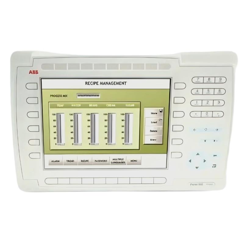
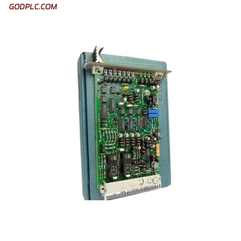
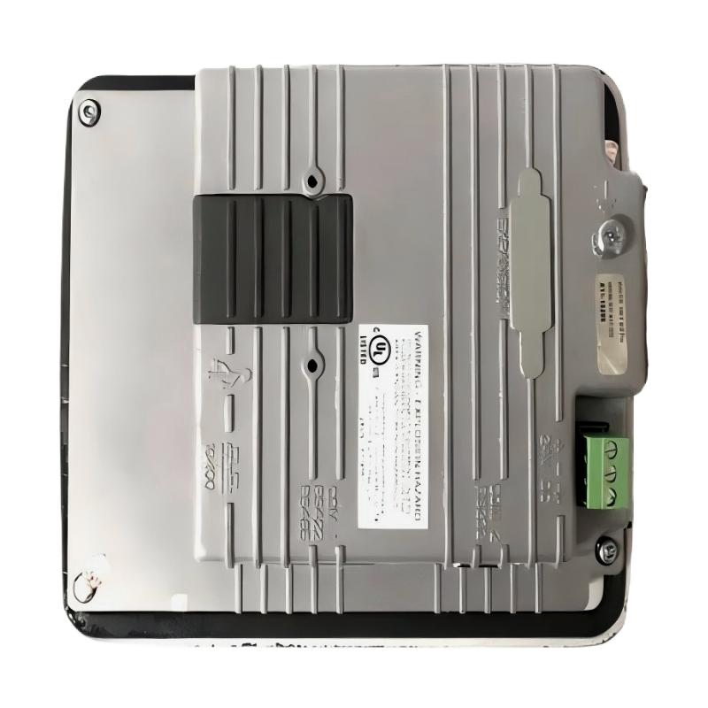
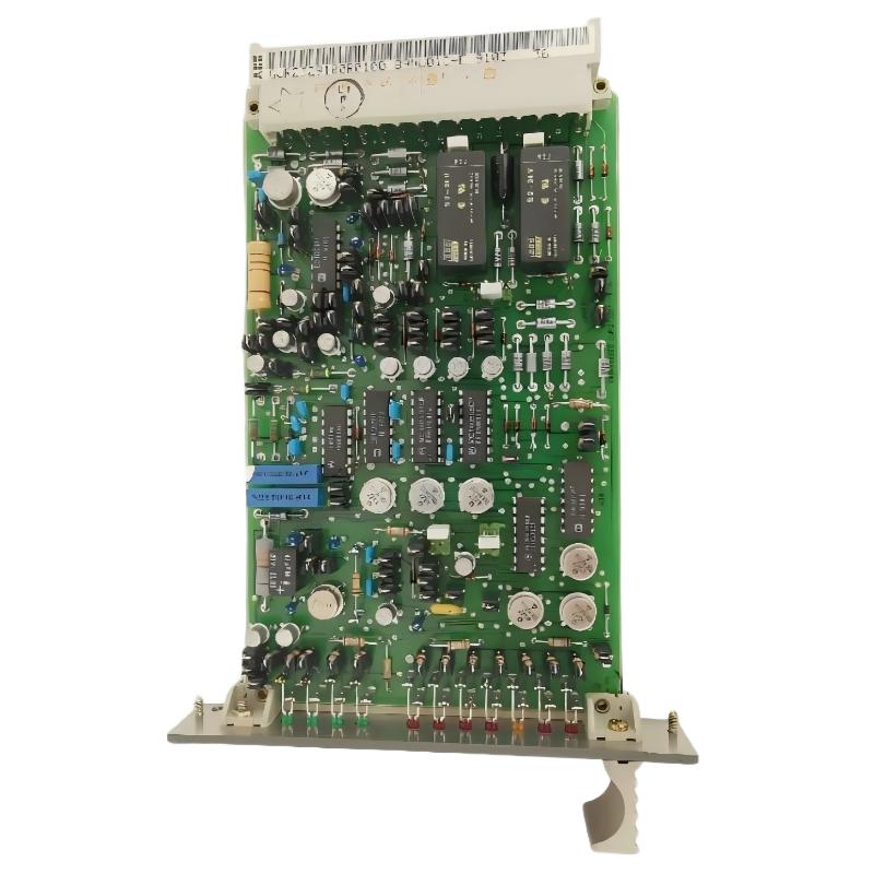
ABB 6011BZ10001C Disk Drive Controller Overview
The ABB 6011BZ10001C Disk Drive Controller should be commissioned as part of the complete control-system architecture rather than treated as an isolated replacement board. Available industrial automation references identify the 6011BZ10001C as an ABB Disk Drive Controller, while other listings associate the part with legacy ABB control-system hardware. Because application-specific documentation can vary by system generation, the safest Installation Guide approach is to verify the installed cabinet, mating connections, firmware or configuration requirements, and the existing controller arrangement before energizing the replacement.
For field engineers, the critical objective is not simply to mount the controller. The objective is to establish a predictable relationship between the controller, its associated drive or disk subsystem, system configuration, power supply, and diagnostic interfaces. This makes Setup and Commissioning considerably easier to validate.
ABB 6011BZ10001C Installation Preparation
Before installation, record the condition of the existing system. A useful engineering record includes the controller identification, cabinet position, cable labels, connector positions, alarm status, and the configuration currently used by the host system.
- Confirm the complete part number is 6011BZ10001C.
- Compare the replacement controller with the removed unit before insertion.
- Photograph connector orientation and cable routing.
- Record existing diagnostic indications before shutdown.
- Verify the approved power isolation procedure for the cabinet.
- Check grounding and bonding before reconnecting the controller.
- Confirm that the system configuration has been backed up where applicable.
A common field mistake is to assume that a physically compatible controller can automatically be substituted without checking the surrounding configuration. In legacy automation systems, configuration data and hardware revision can be just as important as the board itself.
ABB 6011BZ10001C Hardware Installation and Connection
Once the system is safely isolated, inspect the mounting location for contamination, loose hardware, damaged connectors, or signs of overheating. The 6011BZ10001C should be installed using the mechanical arrangement intended for the host cabinet or equipment.
- Isolate the relevant power sources according to the plant safety procedure.
- Verify that the controller position and connector orientation match the original installation.
- Inspect mating connectors for bent contacts, oxidation, or contamination.
- Install the controller without applying excessive mechanical force.
- Reconnect cables according to the recorded identification rather than memory.
- Check cable routing so that signal wiring is not unnecessarily exposed to high-noise power conductors.
- Verify grounding and cabinet bonding before power restoration.
Do not use an assumed pinout simply because another ABB controller has a similar physical appearance. Connector functions must be confirmed from the applicable system documentation for the installation.
ABB 6011BZ10001C System Configuration and Setup
The Setup stage should begin with the controller offline whenever the control architecture permits it. The engineering team should verify that the host system recognizes the expected hardware and that the configuration corresponds to the installed equipment.
- Check controller identification.
- Verify the configured hardware position.
- Review communication or interface parameters.
- Compare configured status with the physical installation.
- Clear obsolete diagnostic conditions only after recording them.
A practical diagnostic sequence can be represented as follows:
READ_CONTROLLER_ID
CHECK_HARDWARE_STATUS
CHECK_INTERFACE_STATUS
VERIFY_SYSTEM_CONFIGURATION
COMPARE_EXPECTED_STATE_WITH_ACTUAL_STATE
CLEAR_ONLY_CONFIRMED_FAULTS
These are engineering pseudo-commands rather than vendor-specific programming commands. They describe the order of verification that should be followed during Fault Diagnosis and commissioning.
ABB 6011BZ10001C Commissioning and Validation
Power should be restored in a controlled manner. The first observation should be the controller’s startup behavior and the status of the surrounding system, not an immediate attempt to place the complete process into automatic operation.
During Commissioning, check for:
- Unexpected controller alarms.
- Interface or communication errors.
- Abnormal power-supply indications.
- Configuration mismatch messages.
- Unexpected drive or subsystem status.
- Intermittent faults appearing after warm-up.
After the initial startup is stable, validate the relevant control functions under controlled conditions. Where possible, compare measured values against the values recorded before replacement. This provides a much better engineering baseline than relying only on a controller status indication.
ABB 6011BZ10001C Commissioning Field Case
In one legacy-control commissioning case involving a replacement controller, the new board powered up normally but the host system did not immediately show the expected subsystem-ready condition. The initial assumption was that the replacement controller was defective.
The investigation was deliberately performed from the system outward. Power at the controller supply was measured at 24.1 VDC, so the supply was not treated as the primary fault. The next check found that one interface connection had been transferred according to its physical location rather than the original cable identification. After restoring the connection to its documented position, the controller was recognized correctly and the abnormal startup indication disappeared.
The important lesson is that a successful power-up does not prove a successful installation. For an ABB 6011BZ10001C Disk Drive Controller, commissioning should confirm hardware recognition, interface integrity, configuration consistency, and actual system behavior.
ABB 6011BZ10001C Installation FAQ
What should be checked before installing the ABB 6011BZ10001C Disk Drive Controller?
Verify the complete part number, existing controller position, connector arrangement, cable identification, power isolation, grounding, and system configuration before installation.
Can the ABB 6011BZ10001C be installed without checking the existing configuration?
No. Hardware installation alone does not guarantee correct system operation. The applicable system configuration and interface arrangement should be verified before commissioning.
Why should the connector wiring be photographed before replacement?
Photographs provide a physical reference during reassembly and reduce the risk of transferring a cable to the wrong interface position.
What is the purpose of checking the controller power supply during commissioning?
Stable supply voltage helps separate controller-related problems from external power problems. A measured value should be evaluated against the requirements of the specific host system.
What should be done if the controller powers up but the system does not recognize it?
Check the interface connections, configured hardware position, system configuration, diagnostic indications, and communication path before concluding that the controller itself has failed.
Is a power-up indication enough to confirm successful commissioning?
No. Successful Commissioning requires functional validation of the controller and the associated subsystem under controlled operating conditions.
ABB 6011BZ10001C Installation Conclusion
The ABB 6011BZ10001C Installation Guide should be approached as a system-level commissioning task. Correct hardware identification, disciplined wiring, configuration verification, controlled startup, and measured validation are more reliable than simply replacing a board and checking whether it powers on. When these engineering checks are performed in sequence, the risk of configuration-related and connection-related commissioning faults is significantly reduced.