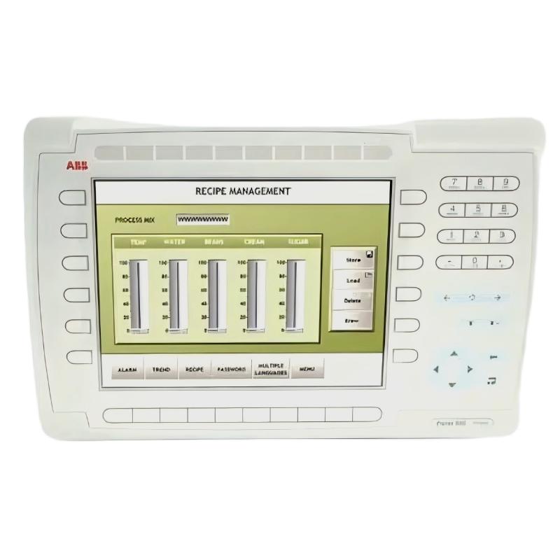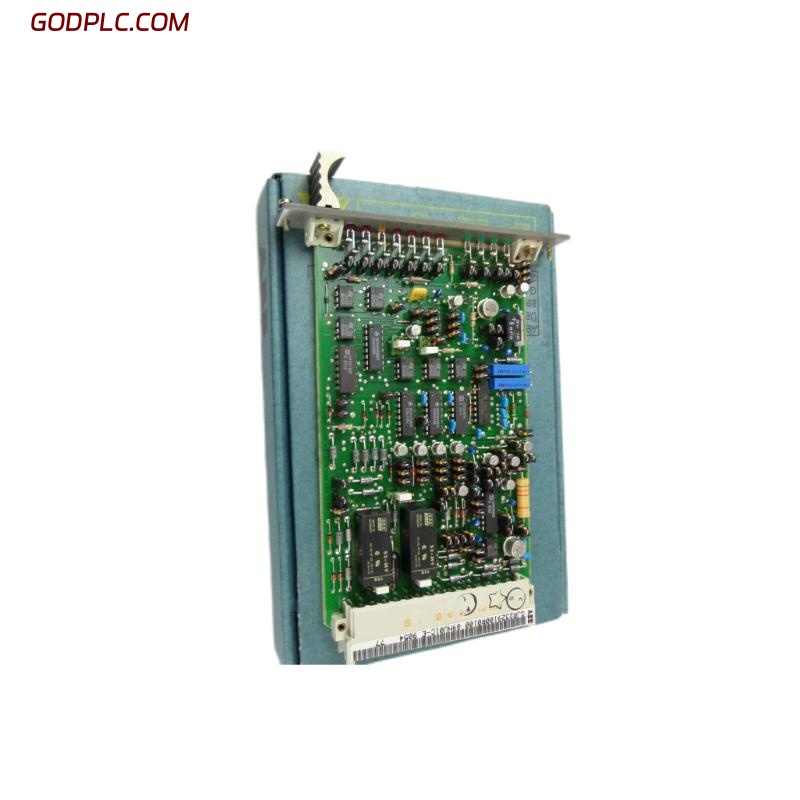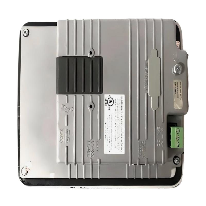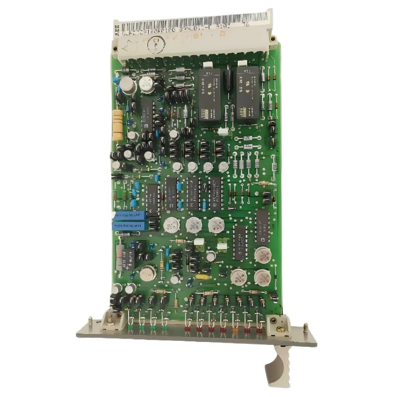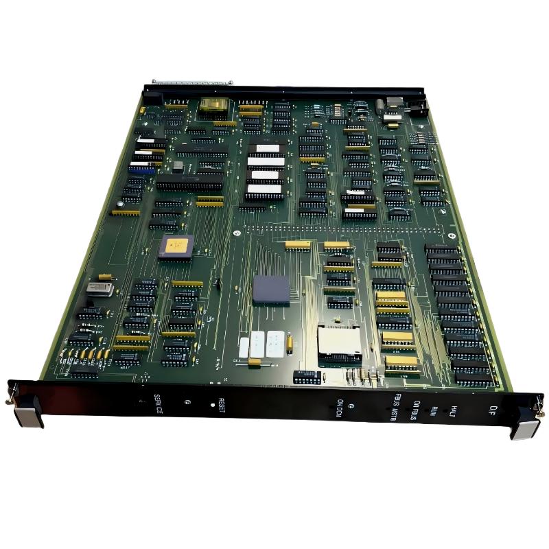
ABB 6205BZ10000G Numeric Input Module Installation Guide
ABB 6205BZ10000G Numeric Input Module installation should begin with signal verification and system configuration, not with terminal wiring alone. Before commissioning, the engineer should confirm the module identity, I/O architecture, field signal type, power conditions, and controller configuration so that an incorrect numeric interpretation is not mistaken for a hardware fault.
ABB 6205BZ10000G Numeric Input Module Installation Requirements
A practical installation starts by separating three questions: Is the module electrically compatible with the I/O system? Are the field signals suitable for the assigned input channels? Has the PLC Controller been configured to interpret those signals correctly?
- Verify the complete ABB 6205BZ10000G part number before installation.
- Check the applicable rack, carrier, or I/O station arrangement.
- Confirm the controller firmware and System Configuration are compatible with the installed I/O architecture.
- Inspect terminal blocks, connectors, and field cables for mechanical damage.
- Confirm the field device signal characteristics before applying power.
- Separate low-level signal wiring from high-power motor and contactor wiring where practical.
ABB 6205BZ10000G Module Wiring and Signal Preparation
For a Numeric Input Module, wiring quality directly affects the value presented to the PLC. An engineer should not assume that a channel reading of zero automatically means the field device is inactive. The input circuit, common reference, shielding, termination, and configuration all need to be considered.
Before connecting the field conductors, identify each channel and document the intended signal source. A simple channel schedule can prevent commissioning errors when several similar instruments are installed close together.
- Isolate the I/O cabinet according to the plant electrical procedure.
- Identify the module position and corresponding channel numbers.
- Verify signal polarity and common/reference connections.
- Check cable continuity before connecting sensitive electronics.
- Connect the field wiring according to the approved cabinet drawing.
- Inspect every termination for loose strands, incorrect ferrules, or accidental bridging.
ABB 6205BZ10000G PLC System Configuration
The hardware installation is only half of the Setup process. The PLC Controller must recognize the intended I/O position and assign the correct data representation. If the physical channel and software channel do not correspond, a perfectly wired module can still produce apparently incorrect values.
During System Configuration, check the rack position, module type, channel allocation, signal interpretation, diagnostic status, and controller communication state. Avoid changing several configuration parameters simultaneously because this makes Fault Diagnosis considerably harder.
CHECK_IO_STATION
VERIFY_MODULE_POSITION
VERIFY_CHANNEL_ASSIGNMENT
READ_INPUT_STATUS
COMPARE_FIELD_SIGNAL
ABB 6205BZ10000G Setup and Commissioning Checks
Commissioning should progress from the electrical layer toward the application layer. First establish that the module is powered and recognized. Then verify individual channels. Finally compare the module data with the process value displayed by the PLC application.
- Confirm normal module status with no unexpected diagnostic indication.
- Activate one known field input at a time.
- Compare the physical input condition with the corresponding PLC value.
- Repeat the test for each required channel.
- Record abnormal channels instead of immediately replacing the module.
ABB 6205BZ10000G Installation Validation in the Field
In one commissioning case involving a numeric input installation, the first test showed that several channels remained at the same value even when the field devices were operated individually. Instead of replacing the module, the engineer compared the channel schedule with the cabinet termination drawing. The investigation showed that two field conductors had been landed on adjacent terminals.
After correcting the termination and repeating the point-to-point test, the input values followed the field-device states correctly. This type of observation is important because an apparent module problem can originate from wiring or channel allocation.
ABB 6205BZ10000G Installation Troubleshooting Points
If commissioning does not produce the expected input data, use a layered Troubleshooting approach. Start with the field signal, then wiring, module status, controller configuration, and finally application logic.
- No channels respond: inspect module recognition, power, common reference, and station configuration.
- One channel is incorrect: inspect its field wiring and terminal assignment first.
- Values appear shifted between channels: check channel mapping and termination order.
- Input changes physically but not in software: verify configuration and PLC data addressing.
- Intermittent readings occur: inspect loose terminals, shielding, grounding, and electrical interference.
ABB 6205BZ10000G Installation FAQ
What should be checked before installing the ABB 6205BZ10000G Numeric Input Module?
Confirm the exact module identification, compatible I/O architecture, field signal requirements, wiring documentation, and PLC System Configuration before energizing the installation.
Why is channel mapping important during ABB 6205BZ10000G commissioning?
Incorrect channel mapping can make a correctly wired input appear on the wrong PLC address. The physical terminal assignment and software channel allocation should therefore be checked together.
How can an engineer verify an ABB 6205BZ10000G input during commissioning?
Apply a known field condition to one channel at a time and compare the physical state with the corresponding PLC input value. Record the result for each required channel.
What causes incorrect numeric values after installation?
Possible causes include incorrect wiring, unsuitable signal conditions, wrong channel configuration, common-reference problems, electrical interference, or incorrect PLC data interpretation.
ABB 6205BZ10000G Installation Guide Conclusion
The most reliable ABB 6205BZ10000G Installation Guide approach is to validate the complete signal path rather than treating the Numeric Input Module as an isolated component. Correct wiring, accurate System Configuration, controlled commissioning tests, and documented channel verification provide the strongest basis for stable PLC operation.
General Note: Actual terminal assignments, electrical limits, compatibility, and configuration parameters should always be verified against the applicable ABB technical documentation and the specific control-system design before field installation.