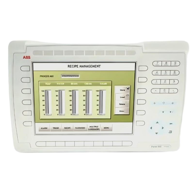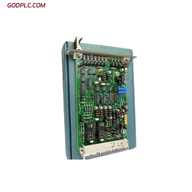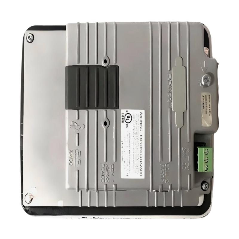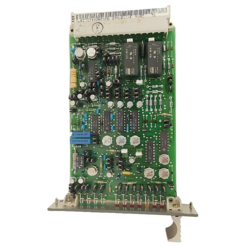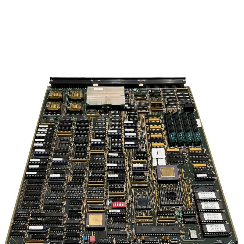
ABB 6204BZ10100D CPU Module Installation Guide
ABB 6204BZ10100D CPU Module installation should focus first on power integrity, rack compatibility, communication wiring, and System Configuration. A CPU that powers up normally but fails to establish communication is often affected by configuration or wiring rather than an immediate CPU hardware failure.
ABB 6204BZ10100D CPU Module Installation Preparation
Before beginning the Setup or Commissioning work, confirm the module identification, mounting position, backplane or rack arrangement, and available power supply. The CPU should be installed only in a system for which the electrical and mechanical interfaces have been verified.
- Check the complete 6204BZ10100D part number and hardware revision.
- Inspect the module connector, terminal area, and PCB for contamination or mechanical damage.
- Verify the control cabinet power supply and protective grounding.
- Confirm that the rack or backplane is suitable for the installed CPU architecture.
- Prepare the approved engineering software and System Configuration data.
- Record the original configuration before modifying an existing control system.
ABB 6204BZ10100D CPU Module Wiring and Power Checks
Good wiring practice is particularly important during an Installation Guide procedure because a CPU can appear defective when the actual problem is unstable power or a poor connection. Keep signal wiring separated from high-current switching conductors where cabinet design permits.
Measure the supply at the module-side connection rather than relying only on the power supply display. During commissioning, observe the voltage during startup and when contactors, drives, or other inductive loads operate.
- Check supply polarity where applicable.
- Verify protective earth and cabinet bonding.
- Inspect connector seating and backplane engagement.
- Check for loose terminals or oxidized contacts.
- Keep communication cables away from high-noise power conductors.
ABB 6204BZ10100D CPU Module Setup and System Configuration
The Setup stage should be completed before transferring a control application. Verify the CPU identity, rack position, communication parameters, I/O assignments, and firmware compatibility according to the actual automation platform.
A practical engineering approach is to compare the intended System Configuration with the physical cabinet. If the software shows a CPU in one position while the hardware is installed elsewhere, downstream communication and I/O diagnostics can become misleading.
ABB 6204BZ10100D CPU Configuration Checklist
- Identify the CPU and hardware revision.
- Verify the rack or backplane position.
- Load the correct System Configuration.
- Check communication addresses and network parameters.
- Verify connected Module or I/O definitions.
- Save the engineering configuration before commissioning.
ABB 6204BZ10100D CPU Module Commissioning Validation
Commissioning should be performed progressively. First confirm stable power and CPU status, then verify communication, followed by I/O and application-level operation. Avoid introducing several configuration changes at the same time because this makes Fault Diagnosis difficult if the system does not behave as expected.
In one field commissioning situation involving an older CPU-based control cabinet, the initial symptom was intermittent loss of controller communication. The CPU status appeared normal, so the engineer measured the supply at the cabinet distribution point and then at the module connection. The difference became noticeable during load switching. After the supply connection and cabinet grounding were corrected, communication remained stable during repeated startup tests.
ABB 6204BZ10100D Commissioning Test Points
- CPU power-up behavior
- Module and rack recognition
- Communication status
- Input and output response
- Application execution
- Restart and recovery behavior
ABB 6204BZ10100D CPU Module Installation Diagnostics
If diagnostic software is available, record the CPU status before clearing alarms or downloading a new configuration. The diagnostic record provides useful evidence if a later Troubleshooting investigation is required.
CHECK CPU STATUS
CHECK RACK STATUS
CHECK COMMUNICATION STATUS
CHECK I/O STATUS
COMPARE SYSTEM CONFIGURATION
RECORD ACTIVE DIAGNOSTICS
ABB 6204BZ10100D CPU Module Installation FAQ
Can the ABB 6204BZ10100D CPU Module be commissioned immediately after installation?
Commissioning should begin only after the physical installation, power supply, rack position, communication interfaces, and System Configuration have been checked against the actual control cabinet.
Why should the supply voltage be checked at the CPU module?
Voltage measured at the power supply may not represent the voltage reaching the CPU. Cable resistance, loose terminals, connectors, and switching loads can cause a local voltage drop.
What should be recorded during ABB 6204BZ10100D commissioning?
Record the hardware identification, configuration version, CPU status, communication condition, measured electrical values, alarms, and important commissioning observations.
ABB 6204BZ10100D CPU Module Installation General Overview
A successful ABB 6204BZ10100D CPU Module installation is not simply a matter of mounting the hardware and applying power. Reliable Setup and Commissioning require verification of electrical conditions, rack compatibility, System Configuration, communication, and application behavior. A measured and progressive commissioning method also creates a useful baseline for future Troubleshooting and Fault Diagnosis.