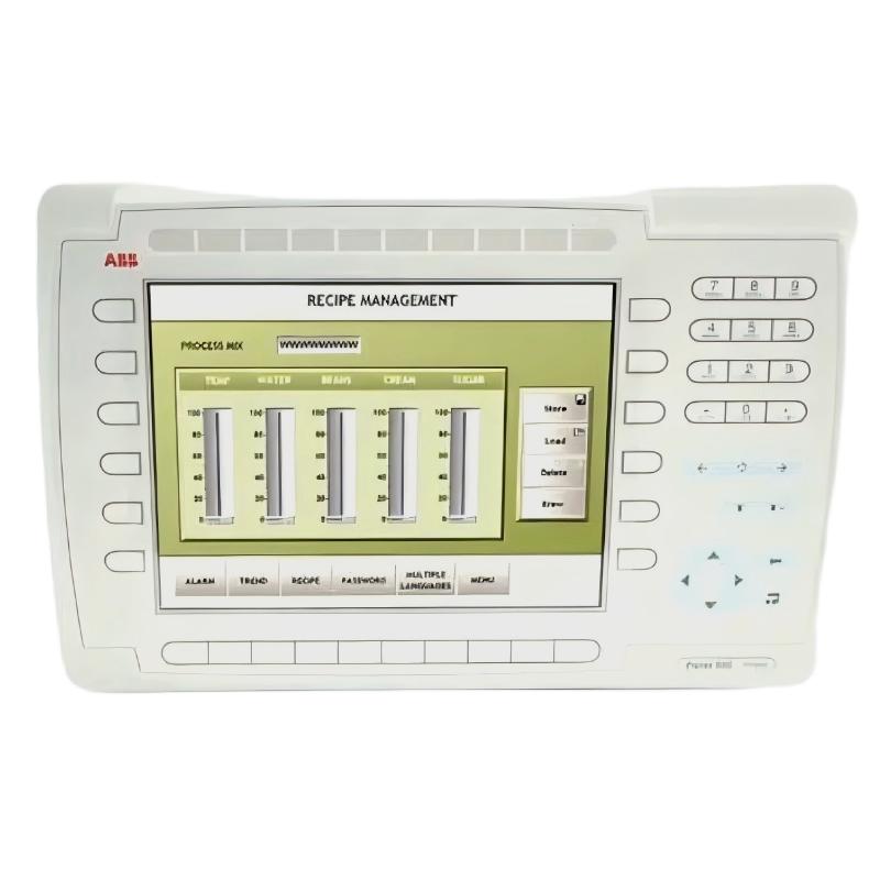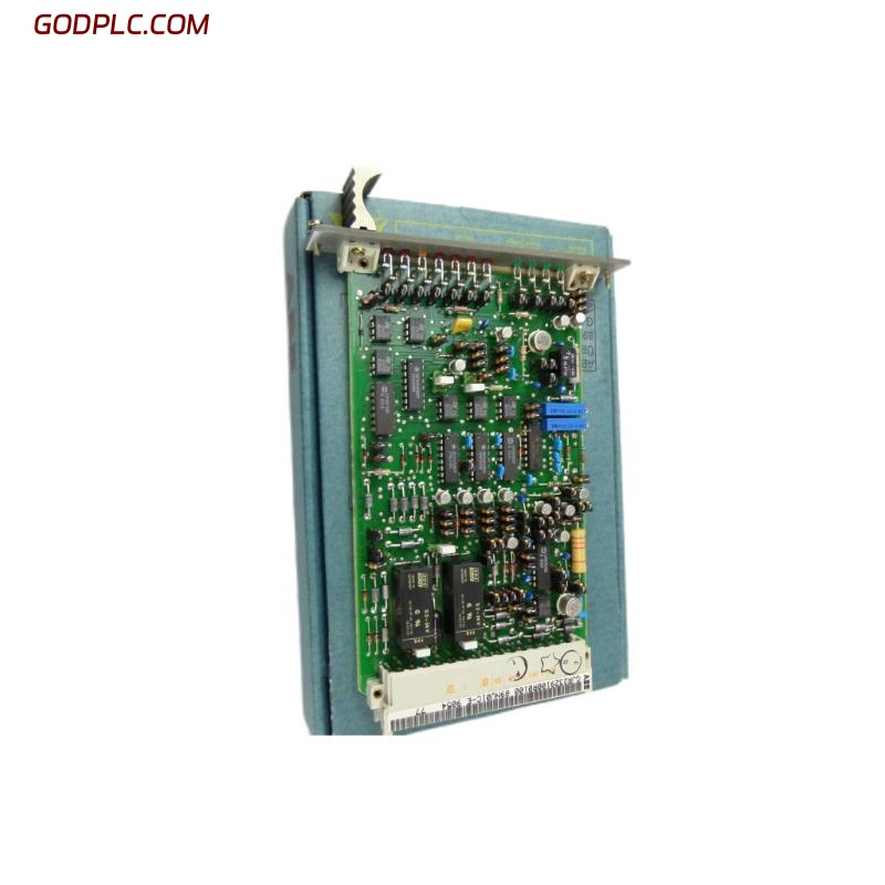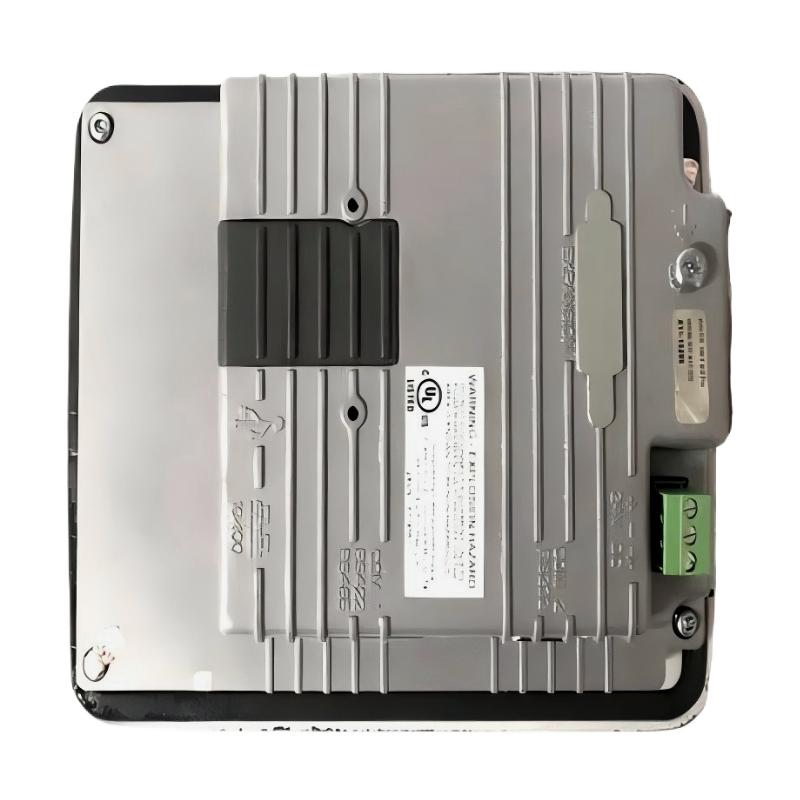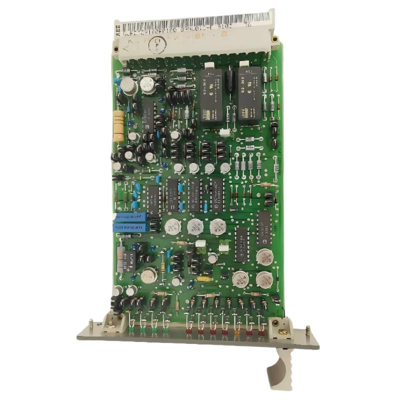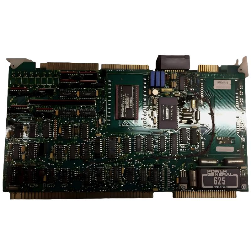
ABB 6101BZ10010A Analog Input Expansion Board installation should begin with hardware identification, cabinet isolation, signal-path inspection, and system configuration rather than immediate power-up. The board is listed as an ABB Analog Input Expander Board, so commissioning work should focus on correct board identification, interface integrity, analog signal quality, grounding, and verification of the host control system before the process is returned to automatic operation.
ABB 6101BZ10010A Analog Input Expansion Board Role
The ABB 6101BZ10010A is identified in available industrial automation listings as an Analog Input Expander Board. In practical terms, an analog expansion board has to be treated as part of a complete measurement chain: field transmitter, cable, termination, board interface, controller processing, and engineering-system scaling all influence the final process value.
This is important during an Installation Guide because a board can be electrically healthy while the displayed process value is still incorrect. A 4–20 mA transmitter, for example, may produce a valid current while the control system interprets the channel with an incorrect range, engineering unit, or channel assignment.
ABB 6101BZ10010A Installation Preparation and Hardware Checks
Before installing the ABB 6101BZ10010A Analog Input Expansion Board, record the identification information from the existing assembly and compare the replacement with the approved system documentation. The exact host-system slot and interface arrangement should be confirmed from the equipment documentation rather than inferred from the board part number alone.
- Record the complete part number: 6101BZ10010A.
- Compare the replacement board with the removed assembly.
- Inspect connectors for bent, contaminated, or recessed contacts.
- Check the cabinet for excessive dust, moisture, or loose conductive material.
- Confirm the control cabinet is isolated according to the site’s lockout procedure.
- Document existing channel assignments before disturbing field wiring.
A useful field practice is to photograph the installed board and termination arrangement before removal. This prevents a common commissioning problem: the hardware replacement is correct, but one field conductor returns to the wrong analog channel.
ABB 6101BZ10010A Analog Input Signal Wiring Checks
Analog input wiring should be checked as a complete circuit. Do not diagnose the 6101BZ10010A only by looking at the board connector. Verify the transmitter supply, signal conductor, return path, shielding, cabinet grounding, and termination points.
- For current-loop instrumentation, confirm the loop is complete before applying power.
- For voltage signals, verify the signal reference is compatible with the host system.
- Keep low-level analog wiring separated from high-current switching conductors.
- Inspect cable shields for incorrect bonding or accidental signal-current paths.
- Check terminal tightness and look for oxidation on older installations.
Do not assume that every analog channel uses the same signal type. The approved system drawings and configuration records should determine the expected input type, range, channel assignment, and termination arrangement.
ABB 6101BZ10010A System Configuration and Setup
The Setup stage should be performed only after the physical installation has been checked. The engineering configuration should match the actual channel arrangement. Pay particular attention to channel numbering because an apparently incorrect analog value can result from an addressing mismatch rather than a defective Analog Input Expansion Board.
Verify the following configuration items:
- Board or module recognition by the host control system.
- Correct analog channel assignment.
- Expected signal type and measurement range.
- Engineering-unit scaling.
- Alarm limits and signal-quality handling.
- Fail-state or diagnostic behavior defined by the application.
Where configuration software provides diagnostic information, compare the hardware status with the engineering database before modifying parameters. Changing several configuration values at once makes later Fault Diagnosis considerably harder.
ABB 6101BZ10010A Commissioning and Analog Signal Validation
Commissioning should progress from the physical layer toward the control application. First establish that the board is recognized, then confirm the electrical input, and finally verify the process value displayed by the control system.
- Confirm cabinet power and system status are within the approved operating conditions.
- Check board recognition and available diagnostics.
- Measure the field signal using a calibrated instrument.
- Compare the measured signal with the engineering-system value.
- Apply a controlled signal change where the process permits it.
- Confirm the displayed value follows the expected direction and scale.
- Return the control loop to normal operating mode.
Commissioning logic:

IF board_status != "healthy"
    inspect hardware and interface
ELSE IF field_signal != expected_signal
    inspect transmitter, wiring and termination
ELSE IF displayed_value != scaled_value
    inspect system configuration
ELSE
    validate process response
ABB 6101BZ10010A Field Commissioning Case
In one analog-input commissioning investigation, the measured transmitter loop was approximately 12.1 mA, while the operator display remained close to the lower end of the configured process range. The first assumption was a faulty input board, but the board diagnostics did not indicate a hardware failure.
The engineering team then traced the signal path from the field termination to the controller database. The physical loop was stable, but the channel assignment in the system configuration did not correspond to the conductor position used during the replacement work. After correcting the channel mapping, the displayed process value followed the measured input consistently.
The important engineering lesson was that replacing a board was not the same as completing commissioning. The signal had to be proven at three points: field measurement, board input, and software interpretation.
ABB 6101BZ10010A Installation and Commissioning FAQ
What should be checked first when installing the ABB 6101BZ10010A?
Start with part-number identification, physical condition, approved slot or mounting location, connector condition, and the existing field-channel documentation. Do not energize an unverified replacement board.
Why can an analog input be wrong even when the ABB 6101BZ10010A is healthy?
Incorrect channel mapping, scaling, transmitter wiring, grounding, signal type, or engineering configuration can all produce an incorrect process value without a board hardware failure.
Should the ABB 6101BZ10010A configuration be changed during initial commissioning?
Only when the approved system configuration requires it. Record the original configuration before making changes and validate one parameter group at a time.
How can an analog signal be verified during commissioning?
Use a calibrated measurement instrument at an appropriate point in the signal circuit and compare the measured value with the value reported by the control system. The exact measurement method depends on the installed signal type and system design.
ABB 6101BZ10010A Installation General Overview
The ABB 6101BZ10010A Installation Guide should be treated as an engineering verification process rather than a simple board replacement procedure. Correct hardware identification, disciplined wiring inspection, System Configuration, signal measurement, and controlled Commissioning provide the strongest basis for reliable analog acquisition. When a channel does not behave as expected, proving the signal path from field device to software value is normally more effective than immediately replacing the Analog Input Expansion Board.