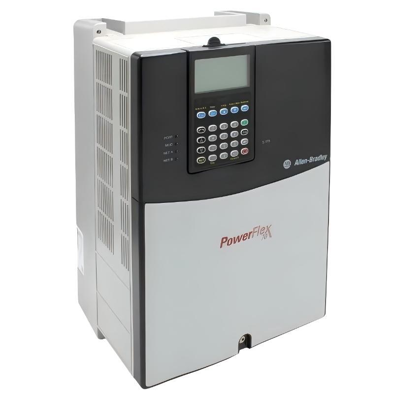
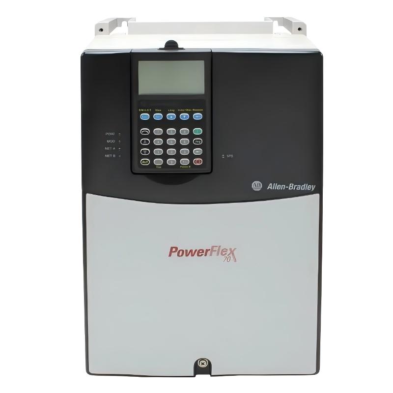
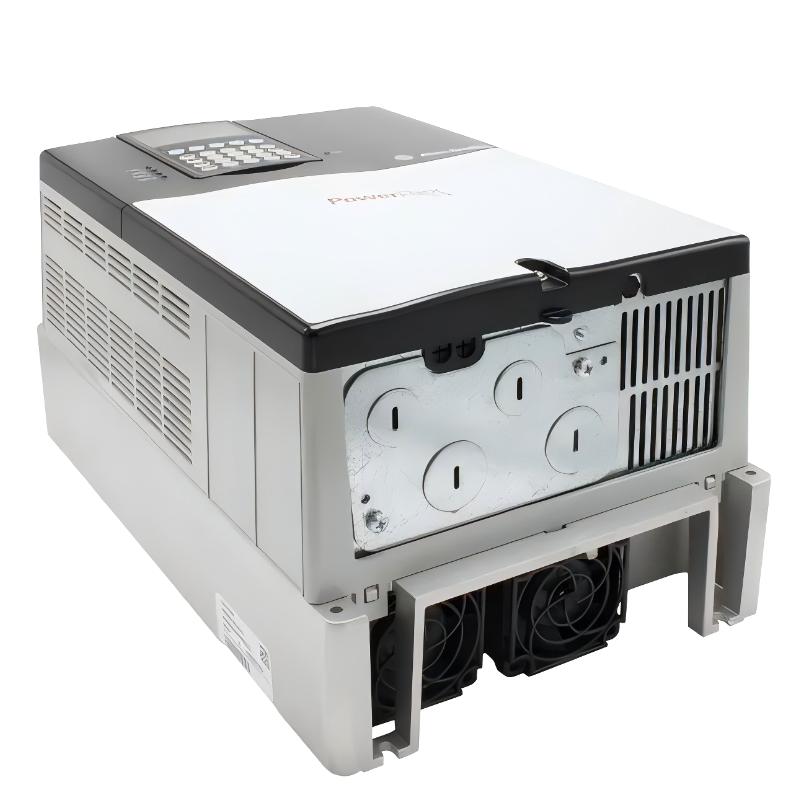
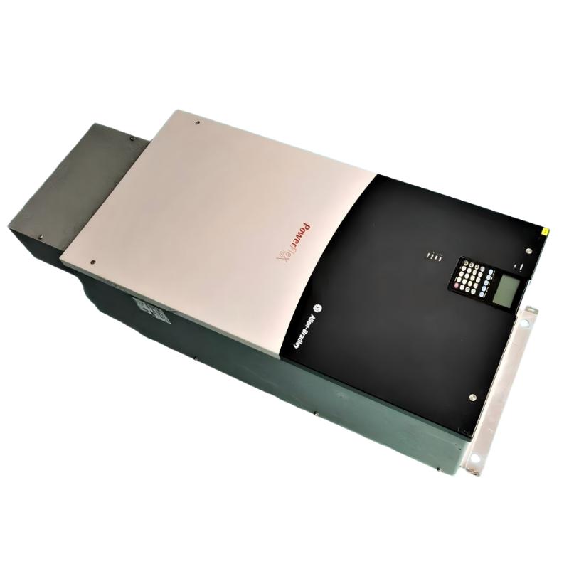
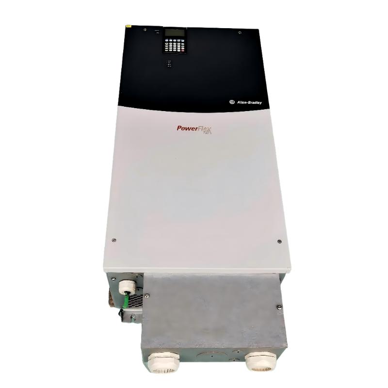
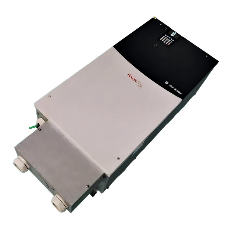
Allen Bradley 20BR180A0ANNANC1 PowerFlex 700 AC Drive
| Company Information | ||||||||
| [email protected] | ||||||||
| Mobile | +8613666084105 | |||||||
| +8613666084105 | ||||||||
| 13666084105 | ||||||||
| Add to | Room 1004, No. 62 Xiangxiu Li, Siming District, Xiamen City, Fujian Province, China | |||||||
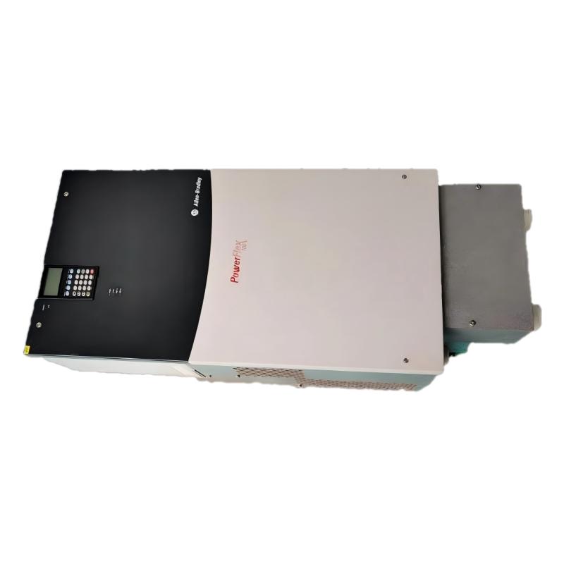 Technical Specifications
| Parameter | Specification |
|---|---|
| Model | 20BR180A0ANNANC1 |
| Product Series | PowerFlex 700 AC Drive 20B |
| Product Type | AC Drive |
| Input Voltage | 650 V DC |
| Input Configuration | DC pre-charge |
| Input Phase | 3-phase |
| Output Phase | 3-phase |
| Continuous Output Current | 180 A |
| 1-Minute Overload Current | 234 A |
| 3-Second Overload Current | 312 A |
| Normal Duty Power | 150 HP |
| Heavy Duty Power | 125 HP |
| Maximum Output Frequency | 420 Hz |
| PWM Carrier Frequency | 2, 4, 8, and 10 kHz |
| Control Method | Vector Control with 24 V DC I/O |
| Motor Control | Sensorless Vector, V/Hz, Vector Control |
| Feedback | Standard Encoder |
| Encoder Type | Incremental, dual-channel |
| Encoder Supply | 12 V DC, 250 mA |
| Digital Inputs | 6 |
| Digital Outputs | 3 |
| Analog Inputs | 2 |
| Analog Outputs | 2 |
| Communication Module | No internal communication module |
| HIM | No HIM, blank plate |
| Brake IGBT | Not included |
| Internal Brake Resistor | Not included |
| EMC Filtering | EMC filter with common-mode choke |
| Enclosure | IP20 / NEMA / UL Type 1 |
| Input Current | 204 A at 650 V DC |
| Fuse Rating | 400 A at 650 V DC |
| Efficiency | Approximately 97.5% at rated current |
| Power Factor | 0.98 |
| Power Ride-Through | 15 ms at full load |
| Overload Capacity | 110% for up to 1 minute; 150% for up to 3 seconds |
| Current Limit | Programmable from 20% to 160% of rated output current |
| Acceleration / Deceleration Time | 0 to 3600 seconds |
| Operating Temperature | 0 to 50 °C |
| Storage Temperature | -40 °C |
| Relative Humidity | 5% to 95%, non-condensing |
| Maximum Altitude | 1,000 m without derating |
| Degree of Protection | IP20 |
| Dimensions | 976.3 × 403.9 × 275.5 mm |
| Weight | 71.44 kg |
FAQ
1. What is the rated output current of the 20BR180A0ANNANC1?
The 20BR180A0ANNANC1 has a continuous output current rating of 180 A at 650 V DC. It is rated for 150 HP under normal-duty operation and 125 HP under heavy-duty operation. The drive can also provide short-term overload capability, reaching 234 A for up to one minute and 312 A for up to three seconds under the specified conditions. When selecting the drive for a motor application, the motor nameplate current should be compared directly with the drive’s current rating. Motor horsepower alone should not be used as the only selection criterion because motor efficiency, voltage, operating speed, load characteristics, and duty cycle can all affect the actual current requirement.
2. What type of motor control is supported by the 20BR180A0ANNANC1?
The 20BR180A0ANNANC1 supports vector-based motor control and can operate with Sensorless Vector, V/Hz, and Vector Control methods. Sensorless Vector Control is useful when the application requires improved speed regulation and torque response without relying on a physical speed feedback device. Vector Control with encoder feedback can provide more precise speed and torque regulation when the application requires closed-loop performance. V/Hz control can be suitable for simpler variable-speed applications where advanced torque regulation is not essential. During commissioning, the motor’s rated voltage, current, frequency, speed, and other relevant parameters should be entered correctly so that the drive can establish an appropriate motor model and provide stable operation.
3. Does the 20BR180A0ANNANC1 have an internal braking resistor or brake IGBT?
The specified 20BR180A0ANNANC1 configuration does not include an internal braking resistor or brake IGBT. This is particularly important for applications involving high-inertia loads, rapid deceleration, frequent stopping, or significant regenerative energy. During deceleration, the motor can return mechanical energy to the drive DC bus, causing the DC bus voltage to rise. If the regenerative energy exceeds the system’s ability to absorb or dissipate it, the drive may generate a DC bus overvoltage fault. For applications with substantial regenerative requirements, the braking system should therefore be evaluated during the engineering stage. The required braking capacity depends on motor speed, load inertia, deceleration time, stopping frequency, and the overall operating cycle.
4. Can the 20BR180A0ANNANC1 use an encoder for closed-loop motor control?
Yes. The specified configuration includes a standard encoder feedback option and supports an incremental dual-channel encoder. The encoder interface is intended for applications where more accurate speed regulation and torque control are required than can normally be achieved with open-loop operation. When installing an encoder, the encoder type, supply voltage, channel configuration, pulse requirements, wiring, shielding, and signal direction should be checked carefully. The encoder feedback must also be configured correctly in the drive parameters. Incorrect encoder wiring or feedback configuration can result in unstable speed, incorrect motor direction, feedback-related faults, or poor low-speed performance. For demanding applications, the encoder should be mechanically mounted with minimal shaft movement and the feedback cable should be routed away from high-power switching conductors where practical.
5. How should the 20BR180A0ANNANC1 be integrated with a PLC or DCS?
The 20BR180A0ANNANC1 can be integrated into an industrial control system using its available control I/O and an appropriate communication option when required. The specified configuration does not include an internal communication module, so the control architecture should determine whether hardwired I/O or an additional communication interface is appropriate. For a hardwired PLC or DCS connection, the engineer should define the start command, stop command, speed reference, drive-ready status, running status, fault indication, and fault-reset logic. Analog reference signals should be configured according to the selected input range, while digital inputs should be assigned according to the required control sequence. Before automatic operation is enabled, the complete command chain should be tested to make sure that the PLC or DCS does not conflict with local drive commands or other control sources.
6. What can cause an overcurrent fault on the 20BR180A0ANNANC1?
An overcurrent fault can result from electrical problems, excessive mechanical load, incorrect motor configuration, or an unsuitable acceleration profile. Typical causes include a motor output short circuit, damaged motor cable, motor insulation problems, a mechanically locked motor, excessive load torque, acceleration that is too aggressive, or incorrect motor nameplate parameters. Troubleshooting should first determine exactly when the fault occurs. A fault immediately after a start command may indicate a wiring, motor, or configuration problem, while a fault during acceleration can point toward excessive load inertia or insufficient acceleration time. The programmed motor current and voltage should be compared with the actual motor nameplate. If the mechanical system is overloaded or partially seized, correcting the mechanical problem is more effective than repeatedly resetting the drive.
7. How can a DC bus overvoltage problem be reduced on the 20BR180A0ANNANC1?
A DC bus overvoltage condition is commonly associated with regenerative energy generated when the motor decelerates. High-inertia machinery, rapid stopping, frequent acceleration and deceleration cycles, and loads that drive the motor can all increase regenerative energy. The first step is to determine whether the fault occurs mainly during deceleration. If this pattern is confirmed, the deceleration time should be reviewed and increased where the machine process allows it. If the required stopping time cannot be increased, the application may require an external braking solution designed to dissipate the regenerated energy. Because the specified configuration does not contain an internal brake resistor or brake IGBT, the braking requirements should be considered separately when designing the complete drive system. The DC bus, braking components, and protection devices should also be checked if the problem continues after the operating profile has been reviewed.
8. What are the main commissioning checks for the 20BR180A0ANNANC1?
Before commissioning, the input power circuit, motor wiring, grounding, control wiring, encoder connection, and protective devices should be inspected carefully. The 650 V DC input requirement must be confirmed, and all power connections should be properly tightened according to the applicable installation requirements. The motor nameplate information should then be entered accurately into the drive, followed by configuration of the selected motor control method and feedback settings. During the initial start-up, the motor should be operated at a controlled speed while checking rotation direction, output current, speed response, acceleration, deceleration, and fault status. If an encoder is used, its feedback signal and direction should also be verified before the machine is placed into automatic operation. For PLC or DCS applications, start/stop commands, speed references, status feedback, fault signals, and emergency-stop functions should be tested individually. The final commissioning should include a representative load test to confirm that the drive remains stable under the actual operating conditions.
Allen Bradley 20BR180A0ANNANC1 PowerFlex 700 AC Drive is in stock. Please contact us for a quick quote and competitive pricing.
| Company Information | ||||||||
| [email protected] | ||||||||
| Mobile | +8613666084105 | |||||||
| +8613666084105 | ||||||||
| 13666084105 | ||||||||
| Add to | Room 1004, No. 62 Xiangxiu Li, Siming District, Xiamen City, Fujian Province, China | |||||||
Company Introduction
Xiamen Shengruite Trading Co., Ltd. is a company specializing in the supply of industrial PLC spare parts.
We provide high-quality PLC spare parts to customers in the global manufacturing, energy and power, chemical and other fields.
Since its establishment in 2011, after 13 years of rapid development, the cumulative global shipments have reached 223,650 pieces, with an annual output value of US$50 million.
Successfully served more than 500 customers in more than 100 countries and regions including Saudi Arabia, UAE, the United States, Europe, Africa, and Southeast Asia
Our Mission
Provide customers with the best quality PLC spare parts and the fastest delivery service to ensure that their industrial automation systems are always in the best operating condition.
We provide a 1-year warranty service, and we support returns and exchanges for any issues to ensure your rights and interests are fully protected.
We can provide detailed product images upon request, and our team can arrange warehouse photos for confirmation to ensure you have all the information you need before making a purchase.
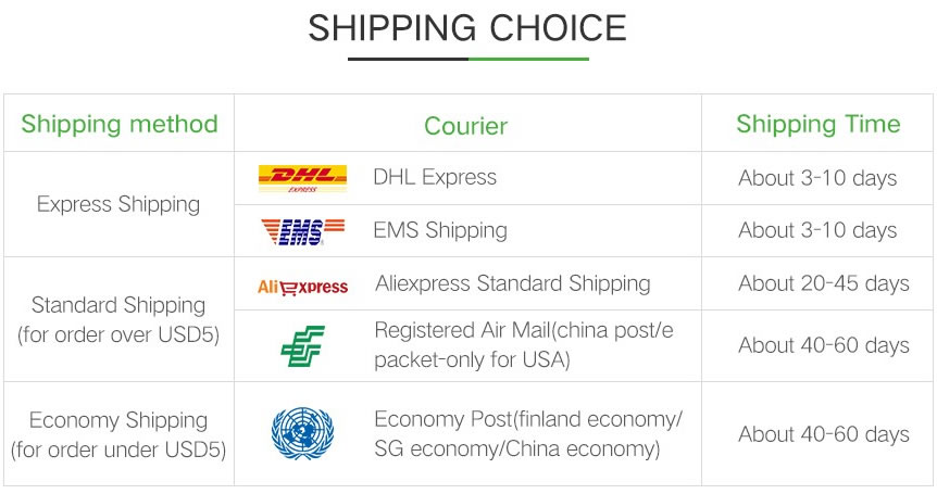
Shipping times vary depending on your location. With the support of our 16 global warehouses, we strive to deliver orders as quickly as possible. Contact us to get an estimated delivery time for your specific location.
The minimum order quantity (MOQ) is typically one unit. However, for larger orders, please contact us for potential discounts and pricing details.
Yes, we offer competitive pricing for bulk purchases. Please reach out to our sales team with the specifics of your order to receive a custom quote.
We accept various payment methods for wholesale orders, including bank transfers (T/T), letters of credit, and other options upon agreement. For large transactions, please contact us directly for payment terms.
Yes, we offer flexible ordering options for both small and large quantities. Whether youre looking for a single unit or a large batch, we can accommodate your needs.
We occasionally offer promotional discounts for new wholesale customers. Contact us to learn more about any current offers available for first-time buyers.
If you are unsure of compatibility with your existing setup please provide your system details and our support team can verify compatibility prior to purchase.
Returns are accepted within 30 days if the product is unused, unopened, and in its original packaging. Please note that return shipping and associated costs are the buyer\\\\\\\\\\\\\\\\\\\\\\\\\\\\\\\\\\\\\\\\\\\\\\\\\\\\\\\\\\\\\\\\\\\\\\\\\\\\\\\\\\\\\\\\\\\\\\\\\\\\\\\\\\\\\\\\\\\\\\\\\\\\\\\\\\\\\\\\\\\\\\\\\\\\\\\\\\\\\\\\\\\\\\\\\\\\\\\\\\\\\\\\\\\\\\\\\\\\\\\\\\\\\\\\\\\\\\\\\\\\\\\\\\\\\\\\\\\\\\\\\\\\\\\\\\\\\\\\\\\\\\\\\\\\\\\\\\\\\\\\\\\\\\\\\\\\\\\\\\\\\\\\\\\\\\\\\\\\\\\\\\\\\\\\\\\\\\\\\\\\\\\\\\\\\\\\\\\\\\\\\\\\\\\\\\\\\\\\\\\\\\\\\\\\\\\\\\\\\\\\\\\\\\\\\\\\\\\\\\\\\\\\\\\\\\\\\\\\\\\\\\\\\\\\\\\\\\\\\\\\\\\\\\\\\\\\\\\\\\\\\\\\\\\\\\\\\\\\\\\\\\\\\\\\\\\\\\\\\\\\\\\\\\\\\\\\\\\\\\\\\\\\\\\\\\\\\\\\\\\\\\\\\\\\\\\\\\\\\\\\\\\\\\\\\\\\\\\\\\\\\\\\\\\\\\\\\\\\\\\\\\\\\\\\\\\\\\\\\\\\\\\\\\\\\\\\\\\\\\\\\\\\\\\\\\\\\\\\\\\\\\\\\\\\\\\\\\\\\\\\\\\\\\\\\\\\\\\\\\\\\\\\\\\\\\\\\\\\\\\\\\\\\\\\\\\\\\\\\\\\\\\\\\\\\\\\\\\\\\\\\\\\\\\\\\\\\\\\\\\\\\\\\\\\\\\\\\\\\\\\\\\\\\\\\\\\\\\\\\\\\\\\\\\\\\\\\\\\\\\\\\\\\\\\\\\\\\\\\\\\\\\\\\\\\\\\\\\\\\\\\\\\\\\\\\\\\\\\\\\\\\\\\\\\\\\\\\\\\\\\\\\\\\\\\\\\\\\\\\\\\\\\\\\\\\\\\\\\\\\\\\\\\\\\\\\\\\\\\\\\\\\\\\\\\\\\\\\\\\\\\\\\\\\\\\\\\\\\\\\\\\\\\\\\\\\\\\\\\\\\\\\\\\\\\\\\\\\\\\\\\\\\\\\\\\\\\\\\\\\\\\\\\\\\\\\\\\\\\\\\\\\\\\\\\\\\\\\\\\\\\\\\\\\\\\\\\\\\\\\\\\\\\\\\\\\\\\\\\\\\\\\\\\\\\\\\\\\\\\\\\\\\\\\\\\\\\\\\\\\\\\\\\\\\\\\\\\\\\\\\\\\\\\\\\\\\\\\\\\\\\\\\\\\\\\\\\\\\\\\\\\\\\\\\\\\\\\\\\\\\\\\\\\\\\\\\\\\\\\\\\\\\\\\\\\\\\\\\\\\\\\\\\\\\\\\\\\\\\\\\\\\\\\\\\\\\\\\\\\\\\\\\\\\\\\\\\\\\\\\\\\\\\\\\\\\\\\\\\\\\\\\\\\\\\\\\\\\\\\\\\\\\\\\\\\\\\\\\\\\\\\\\\\\\\\\\\\\\\\\\\\\\\\\\\\\\\\\\\\\\\\\\\\\\\\\\\\\\\\\\\\\\\\\\\\\\\\\\\\\\\\\\\\\\\\\\\\\\\\\\\\\\\\\\\\\\\\\\\\\\\\\\\\\\\\\\\\\\\\\\\\\\\\\\\\\\\\\\\\\\\\\\\\\\\\\\\\\\\\\\\\\\\\\\\\\\\\\\\\\\\\\\\\\\\\\\\\\\\\\\\\\\\\\\\\\\\\\\\\\\\\\\\\\\\\\\\\\\\\\\\\\\\\\\\\\\\\\\\\\\\\\\\\\\\\\\\\\\\\\\\\\\\\\\\\\\\\\\\\\\\\\\\\\\\\\\\\\\\\\\\\\\\\\\\\\\\\\\\\\\\\\\\\\\\\\\\\\\\\\\\\\\\\\\\\\\\\\\\\\\\\\\\\\\\\\\\\\\\\\\\\\\\\\\\\\\\\\\\\\\\\\\\\\\\\\\\\\\\\\\\\\\\\\\\\\\\\\\\\\\\\\\\\\\\\\\\\\\\\\\\\\\\\\\\\\\\\\\\\\\\\\\\\\\\\\\\\\\\\\\\\\\\\\\\\\\\\\\\\\\\\\\\\\\\\\\\\\\\\\\\\\\\\\’s responsibility.
Yes, we offer technical support for the installation and integration of our products. Our team can assist with setup, configuration, and troubleshooting to ensure a smooth installation.