100% Original, Ready to Ship!

ABB 70EA02A-ES HESG447308R1 Input Module Installation Guide
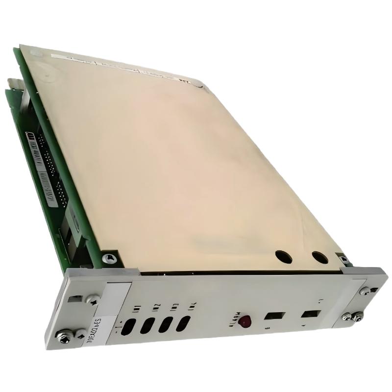
ABB 70EA02A-ES HESG447308R1 Installation Guide Overview
The ABB 70EA02A-ES HESG447308R1 is an ABB Procontrol input module designed for two-wire transmitter signal acquisition. In practical commissioning work, the most important points are correct rack identification, transmitter loop wiring, module power verification, and matching the configured input channel with the actual field signal. The module is commonly identified as a four-channel input interface for two-wire transmitters in the Procontrol P13 system.
ABB 70EA02A-ES Input Module Role in Procontrol System Configuration
Before installing the ABB 70EA02A-ES, confirm that the control cabinet documentation identifies the intended rack position and signal list. The module is not simply a passive terminal interface; it forms the measurement path between field transmitters and the DCS processing system.
- Four-channel input architecture for two-wire transmitter applications.
- Typical field signal: 4–20 mA.
- Integrated transmitter loop supply is associated with the module application.
- Designed for ABB Procontrol P13 installations.
- Each channel should be checked against the plant I/O list before commissioning.
ABB 70EA02A-ES Installation Preparation and System Configuration
Do not begin wiring by relying only on the board label. Compare the hardware identification with the cabinet drawing, I/O database, terminal schedule, and transmitter loop documentation. HESG447308R1 and 70EA02A-ES are both used to identify this input module in available technical references.
- Verify the module part number against the approved spare-parts list.
- Confirm the rack and slot position from the Procontrol cabinet documentation.
- Check that the field transmitter is specified as a compatible two-wire device.
- Inspect terminal wiring for loose conductors, damaged insulation, or incorrect polarity.
- Verify cabinet DC power before connecting the field loop.
ABB 70EA02A-ES Input Module Wiring for Two-Wire Transmitters
For a conventional two-wire transmitter, the current loop must be treated as a complete circuit. A typical engineering check is to verify the transmitter supply, positive loop path, input channel, return path, and cabinet reference rather than measuring only one terminal.
- Identify the transmitter loop associated with Channel 1, 2, 3, or 4.
- Confirm loop polarity before energizing the circuit.
- Keep analog signal wiring separated from high-current switching conductors.
- Check shield termination according to the plant grounding standard.
- Confirm that unused channels are treated according to the site’s I/O termination procedure.
For a 4–20 mA loop, the commissioning engineer should normally expect a measurable current that corresponds to the transmitter process value. For example, approximately 12 mA represents the midpoint of the nominal 4–20 mA span.
ABB 70EA02A-ES Setup and Commissioning Procedure
The safest commissioning sequence is to validate the electrical loop first and the software value second. If the field current is correct but the DCS value is wrong, replacing the module immediately can hide a configuration or termination problem.
- Confirm rack power and module seating.
- Check the transmitter loop with a calibrated meter.
- Apply a known test signal where the plant procedure permits loop simulation.
- Compare the measured current with the value displayed by the control system.
- Check engineering-unit scaling in the System Configuration.
- Verify alarm limits and signal quality indications.
- Return the loop to normal process operation and record the final reading.
CHECK:
Rack Power      = NORMAL
Module Status   = NORMAL
Channel Signal  = 4.00–20.00 mA
DCS Value       = EXPECTED ENGINEERING VALUE
Scaling         = VERIFIED
Alarm Status    = CLEAR
ABB 70EA02A-ES Field Validation and Signal Analysis
A useful field check is to compare three values at the same time: the process instrument output, the current measured at the cabinet, and the value received by the DCS. When all three agree, the signal path is normally behaving as expected.
For example, during a transmitter loop verification, an engineer may inject or simulate 12.00 mA and observe whether the corresponding process value appears consistently in the operator display. If the cabinet meter reads 12.00 mA but the DCS remains near zero, the investigation should move toward channel wiring, configuration, termination, or the input path rather than immediately assuming transmitter failure.
ABB 70EA02A-ES Installation Risks That Affect Commissioning
- Incorrect channel assignment in the I/O database.
- Reversed or interrupted transmitter loop wiring.
- Unwanted electrical noise caused by poor cable routing.
- Incorrect signal scaling in the control configuration.
- Loose rack or terminal connections.
- Using an unsuitable transmitter wiring arrangement.
ABB 70EA02A-ES Installation FAQ
What type of field device is the ABB 70EA02A-ES intended to interface with?
The module is primarily associated with two-wire transmitter applications, particularly analog process measurement loops such as pressure, flow, level, and temperature transmitters.
How should the ABB 70EA02A-ES channel be verified during commissioning?
Verify the actual field current with a calibrated instrument and compare it with the corresponding DCS input value. Channel identification should also match the approved I/O list.
What should be checked before inserting the module into the rack?
Confirm the part number, rack location, power condition, connector condition, and approved installation procedure. The cabinet should be handled according to the plant’s electrical safety requirements.
Why is System Configuration important during ABB 70EA02A commissioning?
The physical current loop can be correct while the displayed engineering value is incorrect because of channel assignment, scaling, range, or database configuration.
How can a 4–20 mA transmitter loop be validated?
Measure the loop current at an approved test point and compare the result with the expected transmitter output. A controlled signal simulation can also be used where permitted by the commissioning procedure.
What is a useful check when the transmitter signal appears unstable?
Compare the transmitter output, cabinet measurement, and DCS value simultaneously. This helps determine whether instability originates in the field instrument, wiring, grounding, or input processing path.
Can a wiring problem be mistaken for an ABB 70EA02A-ES hardware fault?
Yes. Open loops, poor terminations, incorrect polarity, grounding problems, and channel configuration errors can produce symptoms that resemble module failure.
What should be recorded after commissioning?
Record the module identification, channel assignment, measured loop values, DCS readings, alarm status, and any configuration changes made during commissioning.
ABB 70EA02A-ES Installation and Commissioning Summary
A reliable ABB 70EA02A-ES Installation Guide should focus on the complete signal path rather than the module alone. Correct rack placement, verified two-wire transmitter wiring, measured loop current, and matching System Configuration are the key checks before the channel is released for normal operation. The module is documented as a Procontrol input interface for four two-wire transmitter channels, making disciplined loop verification particularly important during commissioning.
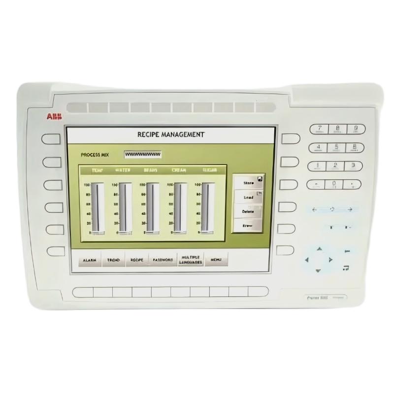 ABB PP845 3BSE042235R1 Operation Panel Installation Guide
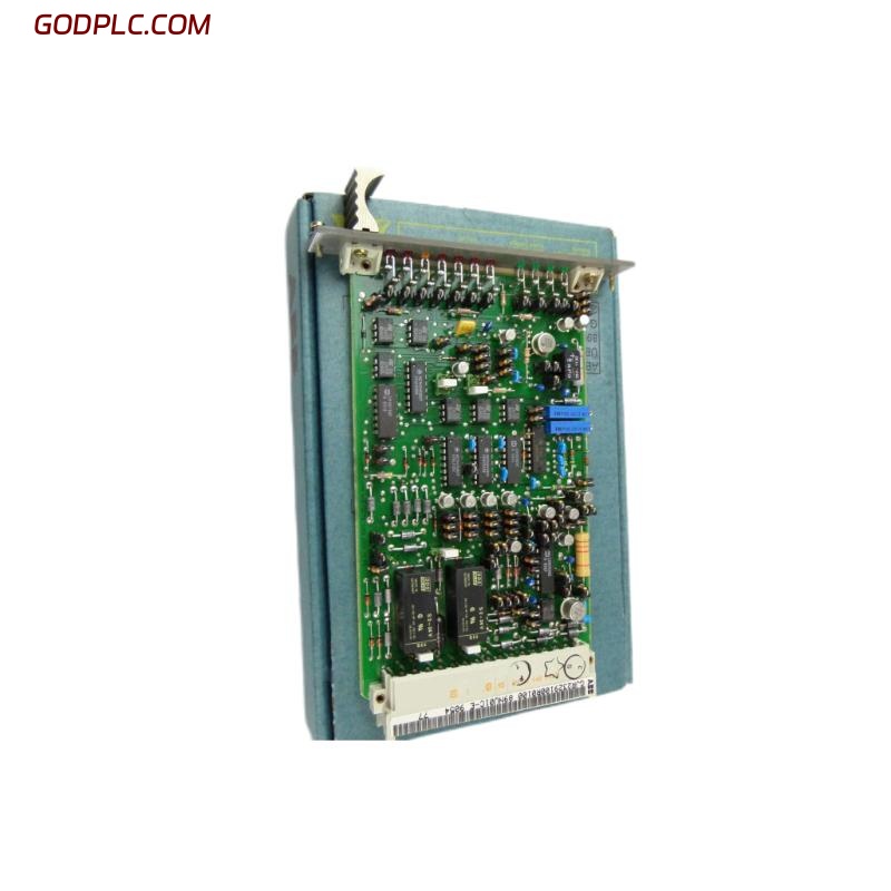 ABB 89NU01E Safety Relay Installation Guide
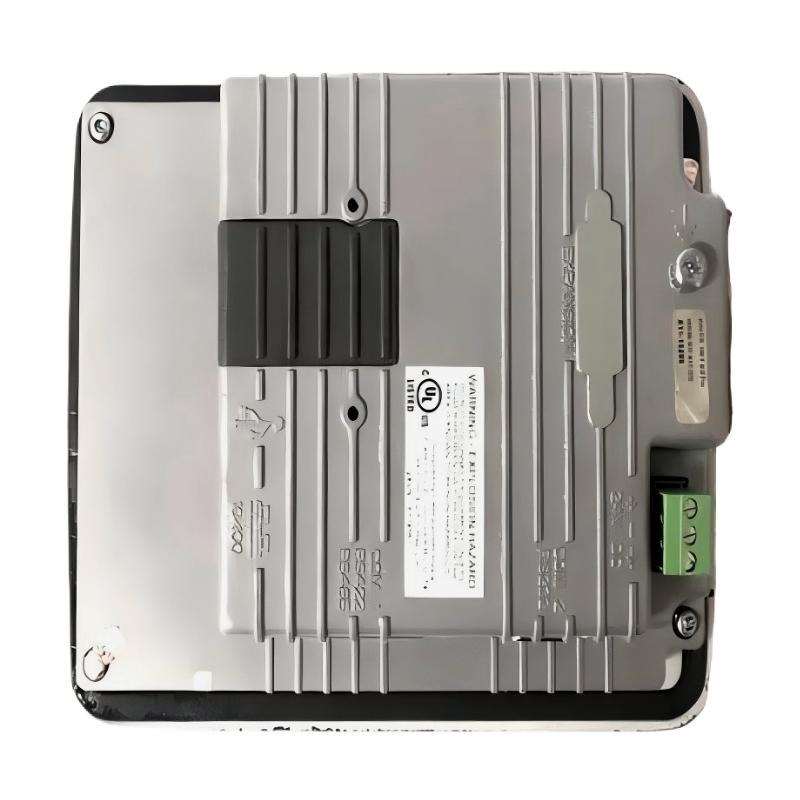 ABB PP825 3BSE042240R1 Operation Panel Installation Guide
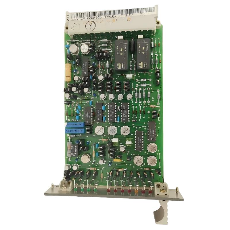 ABB 89NU01D-E GJR2329100R0100 Alarm Module Installation Guide