100% Original, Ready to Ship!

ABB 83SR51 GJR2396200R1210 Control Module Installation Guide
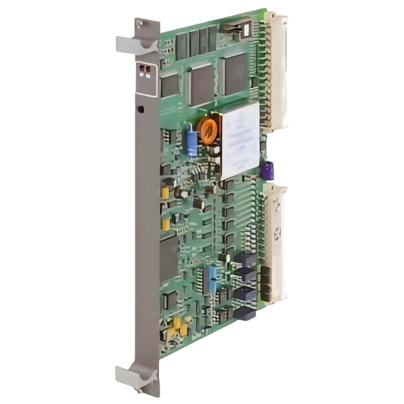
ABB 83SR51 GJR2396200R1210 Control Module Installation Overview
ABB 83SR51 GJR2396200R1210 installation should begin with I/O identification, rack compatibility, signal verification, and Procontrol P14 system configuration rather than simply inserting the module into the rack. The 83SR51R1210 is a Procontrol P14 control module with two control channels; each channel provides 4 digital inputs, 1 digital output, 2 analog inputs, and 1 analog output. ABB documentation identifies the product as GJR2396200R1210 / 83SR51R1210 Control Module. :contentReference[oaicite:0]{index=0}
ABB 83SR51 Control Module Role in Procontrol P14
The ABB 83SR51 is intended for binary and analog control functions and can be applied to electrohydraulic actuators, electropneumatic actuators, and electric motor-driven actuators. Its mixed I/O architecture makes correct channel mapping particularly important during commissioning. :contentReference[oaicite:1]{index=1}
- Product: ABB 83SR51R1210
- Product ID: GJR2396200R1210
- System family: Procontrol P14
- Control channels: 2
- Each channel: 4 DI + 1 DO + 2 AI + 1 AO
- Total inputs: 12
- Total outputs: 2
ABB 83SR51 Installation Preparation and System Configuration
Before installation, compare the module identification label with the engineering documentation. Do not rely only on the short designation 83SR51 because related P14 control modules use similar naming. The complete identification GJR2396200R1210 should be checked against the project bill of materials and the existing system configuration.
Inspect the module for damaged connectors, contamination, bent contacts, loose hardware, or signs of previous overheating. Confirm that the replacement hardware is suitable for the installed Procontrol P14 architecture before applying power.
- Verify module identification and hardware revision.
- Confirm the assigned rack and channel location.
- Review the electrical drawings for every DI, DO, AI, and AO point.
- Check field cable shielding and grounding arrangements.
- Confirm actuator and transmitter signal types.
- Back up the existing application and configuration before modification.
ABB 83SR51 Wiring and Signal Verification
The most common installation mistake with a mixed analog/binary control module is treating every terminal as a generic input or output. The 83SR51 has different signal functions within each control channel, so the engineering drawing should be used to identify the intended point before any field wire is moved.
For analog circuits, verify the transmitter output and receiving channel independently. A loop that appears electrically healthy at the field device can still be incorrectly assigned in the System Configuration.
- Identify the channel and signal number from the engineering drawing.
- Verify the field device supply and return path.
- Measure the signal at the field side before connecting the module.
- Confirm the expected signal range in the control configuration.
- Check digital inputs with the field device in both normal and active states.
- Check output circuits without immediately connecting a critical actuator.
ABB 83SR51 Setup and Commissioning Checks
During Setup / Commissioning, the objective is not merely to prove that the module powers up. The engineer should prove that the configured signal, physical terminal, control logic, and final field response all correspond.
A practical commissioning sequence is to validate one channel at a time. For example, an analog input can first be checked with a calibrated simulator. If the configured input is expected to represent a 4–20 mA signal, a controlled test point such as 12.00 mA provides a useful mid-range validation value. The value shown by the control system should then be compared with the engineering scaling rather than accepted simply because it is non-zero.
CHECK MODULE IDENTIFICATION
CHECK CHANNEL ASSIGNMENT
CHECK FIELD SIGNAL
CHECK CONFIGURED SIGNAL TYPE
CHECK PLC/P14 VALUE
CHECK OUTPUT RESPONSE
CHECK FINAL ACTUATOR RESPONSE
ABB 83SR51 Commissioning Case and Engineering Judgment
In a typical P14 commissioning investigation, an analog process signal may be measured correctly at the field terminal while the operator display remains inconsistent. The correct engineering response is to avoid immediately replacing the 83SR51. First compare the field measurement, channel assignment, configuration scaling, and displayed value.
For example, if a calibrated simulator produces 12.00 mA and the control-system value corresponds to approximately 50% of the configured process range, the input path is behaving plausibly. If the measured field signal is 12.00 mA but the configured channel remains at a fixed or implausible value, the investigation should move toward wiring, channel mapping, configuration, or module hardware.
This diagnostic approach is more reliable than replacing a control module based only on an operator alarm.
ABB 83SR51 Installation Validation and Acceptance
Final acceptance should include both electrical and functional validation. Check the digital inputs under controlled field conditions, verify each digital output, inject representative analog signals, and confirm the analog outputs against the configured command.
- No unexpected module diagnostic condition is present.
- All assigned input channels respond to the correct field device.
- Digital states change consistently with field conditions.
- Analog values track the test signal without unexplained offsets.
- Output commands reach the intended actuator circuit.
- The final System Configuration matches the as-built wiring.
ABB 83SR51 Installation Troubleshooting Prevention
Good installation practice reduces later Troubleshooting work. Record the module identification, configuration revision, measured commissioning values, and channel mapping. This information becomes especially valuable when a P14 control module is replaced during a plant outage.
ABB 83SR51 Installation Guide FAQ
What is the ABB 83SR51 GJR2396200R1210?
It is an ABB Procontrol P14 control module identified as GJR2396200R1210 and 83SR51R1210. The module provides two channels for binary and analog control, with each channel containing 4 digital inputs, 1 digital output, 2 analog inputs, and 1 analog output. :contentReference[oaicite:2]{index=2}
What should be checked before installing the ABB 83SR51?
Verify the complete product identification, rack position, engineering configuration, field wiring, grounding, signal types, and existing application backup before installation.
Why is channel mapping important on the 83SR51?
The module combines digital and analog I/O functions within each control channel. Incorrect channel mapping can produce apparently valid signals on the wrong process point.
How should analog inputs be checked during commissioning?
Use a calibrated signal source or an approved field reference, compare the measured signal with the configured range, and then verify the corresponding process value in the control system.
Can the ABB 83SR51 be used for actuator control?
ABB product information states that the module is suitable for electrohydraulic actuators, electropneumatic actuators, and electric motor-driven actuators. :contentReference[oaicite:3]{index=3}
What is the most important commissioning record?
Record the actual module identification, channel assignment, configuration revision, field measurements, and functional test results. These records greatly simplify later Fault Diagnosis.
ABB 83SR51 Installation Guide Conclusion
A successful ABB 83SR51 GJR2396200R1210 Installation Guide process should prove more than physical installation. The module, field wiring, System Configuration, signal scaling, control logic, and actuator response must agree. Using measured signals and channel-by-channel validation provides a practical Setup / Commissioning method and creates useful reference data for future Troubleshooting.
 ABB PP845 3BSE042235R1 Operation Panel Installation Guide
 ABB 89NU01E Safety Relay Installation Guide
 ABB PP825 3BSE042240R1 Operation Panel Installation Guide
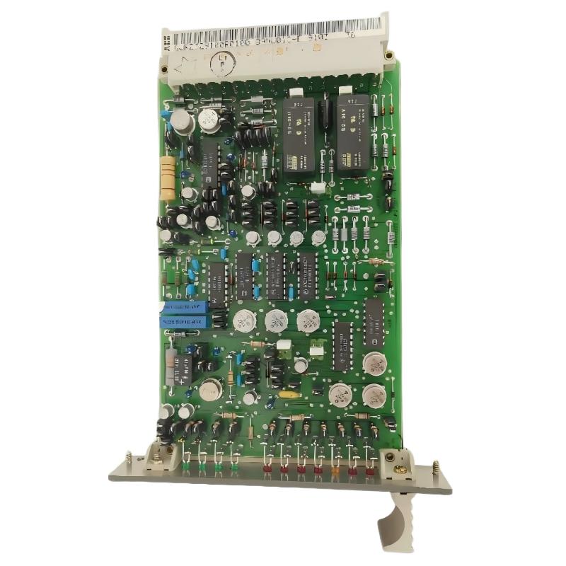 ABB 89NU01D-E GJR2329100R0100 Alarm Module Installation Guide