100% Original, Ready to Ship!

ABB 89AS30 GKWN000317R0100 Analog Signal Multiplier Installation Guide

ABB 89AS30 Analog Signal Multiplier Installation Guide
The ABB 89AS30 GKWN000317R0100 Analog Signal Multiplier should be installed with particular attention to signal compatibility, terminal identification, grounding, and system configuration. Before commissioning, engineers should confirm the device’s actual input and output specifications against the project drawings and the applicable ABB documentation rather than assuming compatibility from the model designation alone.
Contents of the ABB 89AS30 Installation Guide
- Module Role and Application
- Installation Preparation
- Signal Wiring and Grounding
- Setup and Commissioning
- Signal Validation
- Frequently Asked Questions
- General Overview
ABB 89AS30 Module Role in Analog Signal Processing
An analog signal multiplier is generally used to distribute or condition an analog measurement for more than one receiving circuit, depending on its specific design. In a PLC or DCS installation, the engineering objective is to ensure that the signal received by each destination remains within the required measurement range and accuracy limits.
For the ABB 89AS30 GKWN000317R0100, verify the precise function, supported signal types, channel arrangement, and electrical ratings using the correct product documentation. Do not assume that every signal multiplier provides galvanic isolation or supports every standard analog signal.
Installation Preparation and System Configuration
Before mounting or wiring the ABB 89AS30 Analog Signal Multiplier, review the control cabinet drawings and establish where the device sits in the signal path. Record the source instrument, receiving PLC or DCS channels, cable identifiers, and expected engineering units.
- Confirm the complete model number and hardware revision against the approved bill of materials.
- Check the manufacturer’s terminal diagram and specified mounting method.
- Verify input and output signal ranges, supply requirements, and permissible load.
- Check cabinet temperature, available space, and required separation from power wiring.
- Identify the required PLC scaling, alarm thresholds, and signal-failure response.
Isolate the relevant power sources and follow site lockout/tagout procedures before handling terminals. Electrical work should be performed by qualified personnel using approved site procedures.
ABB 89AS30 Analog Signal Multiplier Wiring Considerations
Signal wiring must follow the terminal assignments documented for the exact hardware version. Never infer terminal numbers from another ABB module or a visually similar device.
- Identify the source signal pair and verify its polarity where applicable.
- Connect the source and receiving circuits according to the approved wiring diagram.
- Route analog signal cables away from variable-frequency drives, contactors, and high-current conductors where practical.
- Apply the specified shield termination and grounding method; avoid creating unintended ground loops.
- Check for loose terminals, short circuits, and wiring discrepancies before energizing the system.
For a current-loop application, confirm whether the connected circuits are active or passive and calculate the total loop burden. For voltage signals, check input impedance and common-reference requirements. These details can determine whether the signal remains accurate after connection.
ABB 89AS30 Setup and Commissioning Procedure
Commissioning should start with documented electrical checks rather than immediate integration into the running process. Where the installation permits, test the circuit with the controlled equipment in a safe state.
- Compare the completed wiring with the approved schematic.
- Verify supply voltage at the designated measurement points against the manufacturer’s specified range.
- Apply a known input signal using a calibrated signal source or an approved process simulation method.
- Measure each relevant output independently and compare it with the expected response.
- Confirm that the PLC or DCS displays the correct value after engineering-unit scaling.
- Record the as-found and as-left readings, instrument identification, and calibration equipment details.
Commissioning record (illustrative pseudocode)

VERIFY model_number
VERIFY terminal_wiring_against_drawing
CHECK supply_voltage_within_specification
APPLY known_input_signal
MEASURE each_required_output
COMPARE measured_values_with_expected_values
VERIFY PLC_DCS_scaling_and_alarm_limits
SAVE commissioning_results
The commands above are a commissioning checklist, not executable ABB controller commands. Use the actual site procedures and approved test instruments.
ABB 89AS30 Signal Validation and Acceptance Criteria
A useful validation test includes a low-range, mid-range, and high-range input wherever permitted by the device specifications and process safety requirements. At each point, record the input, each output, the PLC or DCS displayed value, and the measurement uncertainty.
For example, if the approved design specifies a 4–20 mA input, the expected electrical output must be determined from the documented transfer function. Do not assume that the ABB 89AS30 uses this range or that every output reproduces the input identically without checking its datasheet.
In a typical field investigation, a discrepancy between a calibrated source reading and a control-system display should be traced through the signal chain: source instrument, multiplier input, multiplier output, field cable, and PLC input scaling. This approach helps distinguish an installation issue from a configuration or instrumentation problem.
ABB 89AS30 Installation and Commissioning FAQ
What should be checked before installing the ABB 89AS30?
Confirm the full part number, compatible signal types, electrical ratings, terminal layout, mounting requirements, and the applicable ABB documentation. Also verify that the planned receiving circuits are compatible with the device outputs.
Can the ABB 89AS30 be connected directly to any PLC analog input?
No. Compatibility depends on the actual output type, signal range, input impedance or loop burden, grounding arrangement, and the PLC input module specifications.
How should the analog output be tested during commissioning?
Use a calibrated source and suitable measurement equipment to apply known input values. Compare each output with the documented transfer function and confirm that the PLC or DCS display uses the correct scaling.
Why is cable shielding important for an analog signal multiplier?
Correct shielding and routing can reduce electromagnetic interference that may otherwise cause unstable readings. The shield termination method must follow the manufacturer’s instructions and the site’s grounding design.
Does the ABB 89AS30 provide electrical isolation?
Do not assume isolation from the product name alone. Confirm the isolation characteristics and ratings in the official documentation for the exact variant.
What commissioning records should be retained?
Keep the wiring verification, supply measurements, applied test values, output readings, calibration equipment details, scaling checks, deviations, and final acceptance results.
General Overview of ABB 89AS30 Installation
Reliable ABB 89AS30 GKWN000317R0100 installation depends on verified product specifications, correct signal wiring, a compatible PLC or DCS interface, and recorded commissioning tests. Treat the manufacturer’s terminal diagram and electrical ratings as the controlling references. If the device’s exact transfer function or terminal assignments cannot be verified, resolve that documentation gap before connecting it to a live control loop.
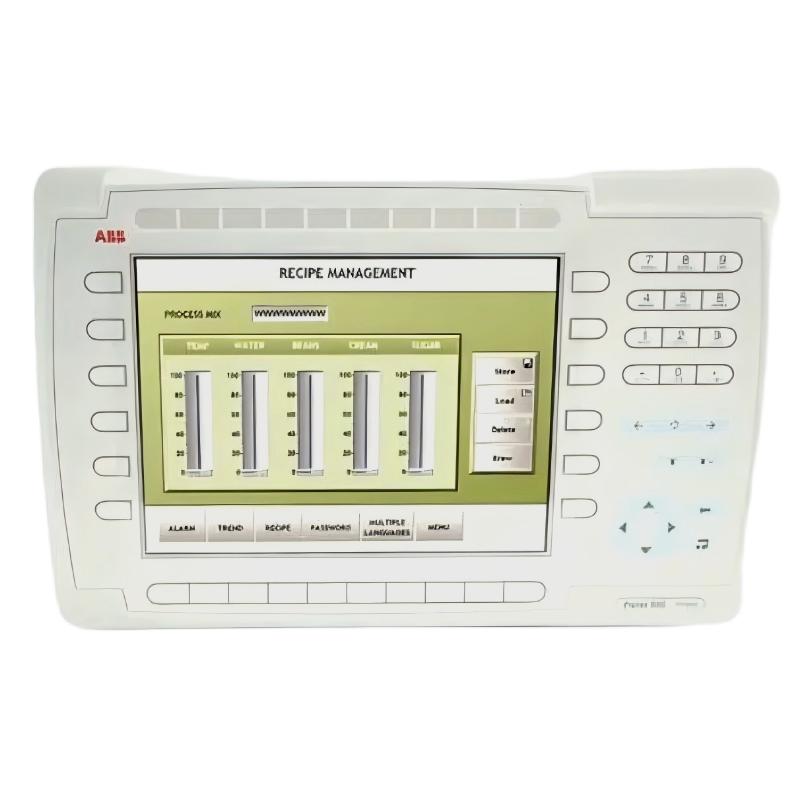 ABB PP845 3BSE042235R1 Operation Panel Installation Guide
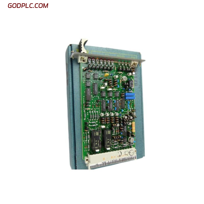 ABB 89NU01E Safety Relay Installation Guide
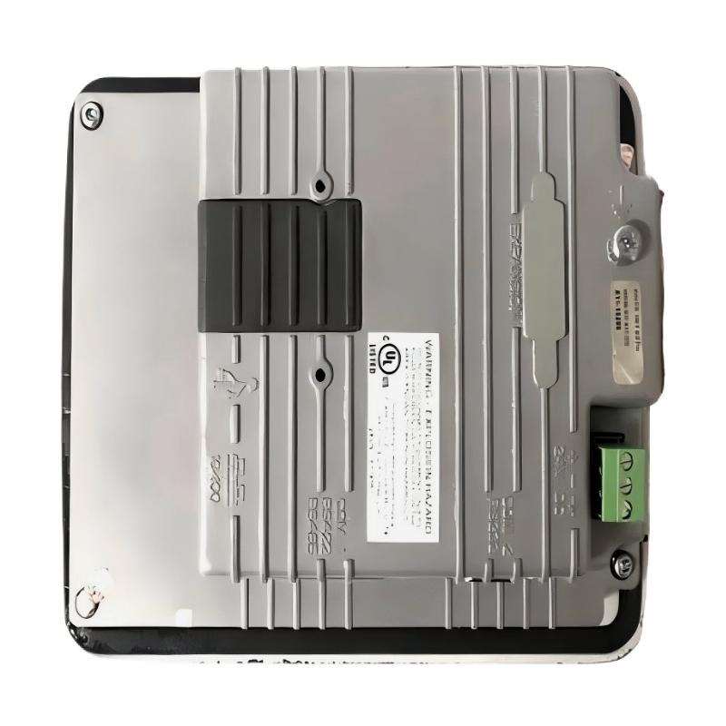 ABB PP825 3BSE042240R1 Operation Panel Installation Guide
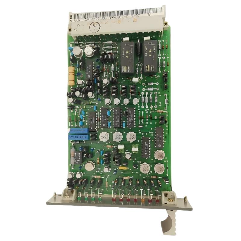 ABB 89NU01D-E GJR2329100R0100 Alarm Module Installation Guide