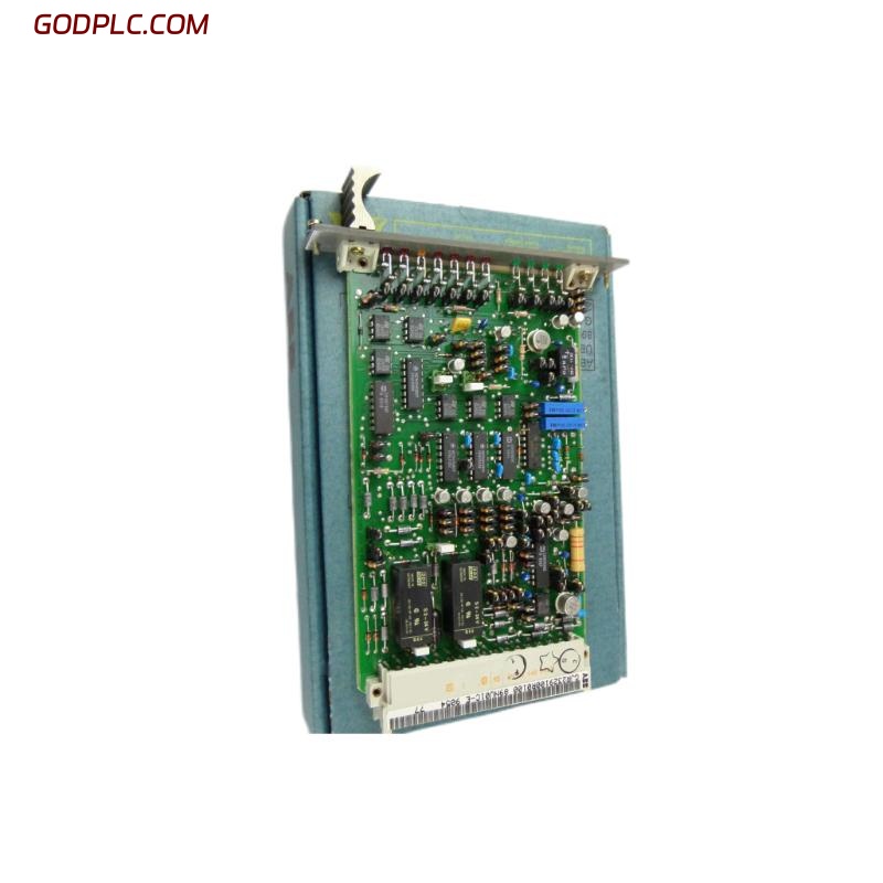
ABB 89NU01E Safety Relay Installation Guide Overview
The ABB 89NU01E safety relay, associated with the 89NU01C-E designation and part number GJR2329100R0100, should be installed only after its exact hardware identity, terminal assignments, and intended safety function have been verified against the applicable ABB documentation. A reliable Installation Guide must cover more than physical mounting: wiring integrity, protective measures, System Configuration, and commissioning checks all affect whether a safety-related circuit can perform as intended.
This guide outlines an engineering workflow for inspecting, installing, and validating the unit. The actual supply voltage, terminal layout, contact ratings, and reset logic must come from the correct manufacturer documentation rather than assumptions based on the model number.
ABB 89NU01E Safety Relay Identification and Preparation
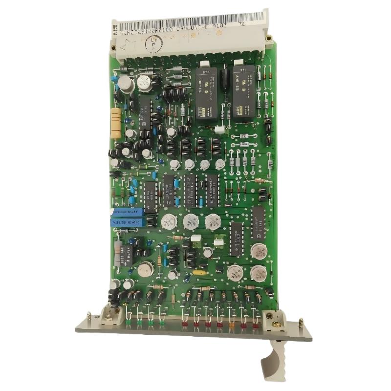
Before beginning work, compare the nameplate and product markings with the purchase record and approved equipment list. The identifiers 89NU01E, 89NU01C-E, and GJR2329100R0100 should not automatically be treated as interchangeable hardware revisions without confirmation.
- Record the complete type designation and part number.
- Inspect the enclosure, connector pins, terminals, and mounting points for physical damage.
- Obtain the correct wiring diagram and technical data for the installed revision.
- Review the machine risk assessment, safety circuit drawings, and required safety performance.
- Isolate all relevant energy sources and apply the site’s lockout/tagout procedure before wiring.
ABB 89NU01E Safety Relay Mounting and Wiring Strategy
Mechanical installation should follow the specified mounting arrangement and environmental limits. Leave sufficient access for inspection and ensure that vibration, heat, moisture, and conductive contamination remain within the product’s documented limits.
For electrical connections, use the verified terminal diagram. Confirm conductor size, insulation rating, terminal torque, protective-earth requirements where applicable, and separation between safety-related circuits and other wiring according to the design documentation and applicable standards.
- Identify supply, input, output, common, and reset terminals only from the correct diagram.
- Check that external contactors or switching devices match the approved circuit design.
- Verify feedback monitoring and manual-reset arrangements where the design requires them.
- Do not bridge safety inputs or bypass interlocks to force the equipment into operation.
ABB 89NU01E Safety Relay Setup and Commissioning Checks
Commissioning should proceed from de-energized inspection to controlled functional testing. Confirm the expected behavior for normal operation, a safety demand, loss of supply, and restoration of power. Test reset behavior and monitored external devices where applicable to the approved design.
- Compare the completed wiring against the approved schematic, terminal by terminal.
- Check continuity and unintended shorts with the equipment safely isolated.
- Verify supply voltage at the specified measurement points against the nameplate and manual.
- Apply power under controlled conditions and observe the documented indicators.
- Test each safety input and confirm that the relevant output changes state as specified.
- Record test results and obtain authorization before returning the machine to service.
Commissioning record — illustrative checklist, not ABB device commands

IDENTITY_CHECK = confirm nameplate and revision
WIRING_CHECK = compare terminals with approved schematic
SUPPLY_CHECK = measure against documented rated voltage
INPUT_TEST = verify each designed safety demand
OUTPUT_TEST = verify specified output response
RESET_TEST = confirm documented reset behavior
RESULT = record pass/fail and technician sign-off
ABB 89NU01E Safety Relay Installation Faults to Prevent
Common installation risks include incorrect terminal identification, loose conductors, an unsuitable supply, undocumented wiring changes, and reset circuits that do not match the safety design. A relay indicator illuminating does not, by itself, prove that the entire safety function is effective.
Field-engineering example: During a hypothetical commissioning exercise, a safety output fails to energize after wiring work. Rather than replacing the relay immediately, the technician isolates the equipment and checks the drawing revision, supply measurement, input states, reset circuit, and external feedback loop in sequence. The example illustrates a diagnostic method; it is not a verified field report for this model.
ABB 89NU01E Safety Relay Installation FAQ
What should be checked before installing the ABB 89NU01E?
Verify the full product designation, GJR2329100R0100 part number, applicable hardware revision, approved circuit drawing, and manufacturer specifications before connecting any conductors.
Can the ABB 89NU01E be commissioned using a generic safety relay wiring diagram?
No. Terminal assignments, operating voltage, contact configuration, and reset requirements must be confirmed from documentation applicable to the exact unit and revision.
How can the safety relay’s commissioning results be documented?
Record identification, wiring inspection, supply measurements, input and output tests, reset behavior, external-device feedback checks where applicable, and the final acceptance decision.
ABB 89NU01E Safety Relay Installation Conclusion
A dependable ABB 89NU01E Installation Guide combines correct product identification, controlled wiring, verified System Configuration, and documented Setup / Commissioning tests. Because this is a safety-related component, successful installation must be demonstrated through the complete safety function—not inferred from an indicator light or an isolated output test. If the correct terminal diagram or technical limits are unavailable, stop and obtain the applicable ABB documentation before energizing the circuit.