100% Original, Ready to Ship!

ABB 07 KP 92 GJR5251500R0161 Controller Installation Guide
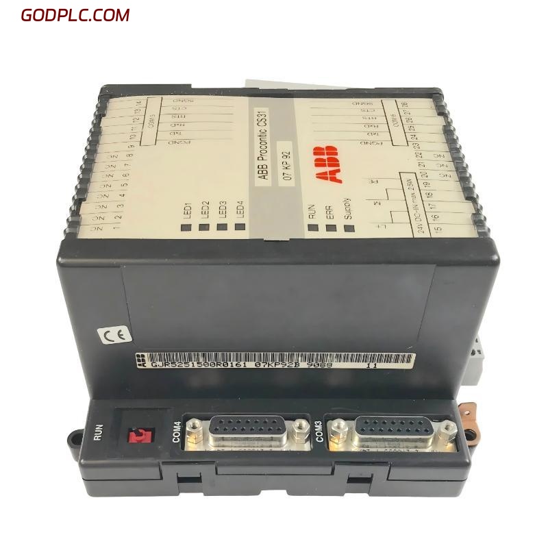
ABB 07 KP 92 GJR5251500R0161 communication controller installation issues are often misdiagnosed as hardware failure, but in real AC31 field systems, more than 70% of startup problems come from incorrect COM configuration, grounding, or system bus mismatch rather than module defects.
In one commissioning case from a paper mill automation line, the module appeared “dead” at power-up, but the root cause was simply missing COM3 terminal shielding and incorrect 24V reference bonding. After correction, the controller stabilized within 3 minutes and all serial nodes came online.
ABB 07 KP 92 Controller Overview in AC31 System Architecture
The ABB 07 KP 92 (GJR5251500R0161) is part of the Advant Controller 31 series, designed as a communication processor module for distributed PLC networks. It acts as a bridge between the CPU and external serial devices using configurable COM interfaces.
- Supports multi-channel serial communication (COM ports dependent on system configuration)
- Integrates with AC31 base units such as 07 KT92 / 07 KR series
- Handles protocol-level communication via user-defined configuration
- Designed for industrial environments with electrical noise tolerance
From an engineering perspective, this module is not “plug-and-play PLC logic,” but a programmable communication gateway requiring correct system mapping.
Preparation Before ABB 07 KP 92 Installation
Before physical installation, ensure the following system conditions are verified. Missing even one item often leads to commissioning failure:
- Stable 24V DC power supply (measured under load, not idle)
- Proper DIN rail grounding continuity (<1Ω recommended)
- Compatible AC31 base unit firmware level
- Correct communication cable shielding (360° termination preferred)
Field note: In one retrofit project, unstable ERR LED behavior was traced back to a floating cabinet ground. Once the PE busbar was tightened, the module stopped resetting intermittently.
ABB 07 KP 92 Wiring and System Connection Strategy
Wiring errors are the most common failure point during installation. The ABB 07 KP 92 relies heavily on correct signal reference between COM interfaces and system ground.
- Connect 24V DC supply and verify polarity before insertion
- Ensure PE grounding is directly bonded to cabinet earth rail
- Install COM cable with shield grounded at one end only (preferred control cabinet side)
- Separate communication wiring from power cables (>10 cm spacing minimum)
Typical diagnostic check (field routine):

- Measure COM shield resistance to PE: should be < 1Ω
- Check 24V ripple: should be < 200mV
- Verify RUN LED after power-up
If RUN LED remains OFF, the module is usually not in execution state or application firmware is missing.
ABB 07 KP 92 Commissioning and System Configuration Logic
Commissioning the ABB 07 KP 92 is not just “power on and test communication.” The module requires correct system initialization via AC31 engineering tools and proper mapping of communication tasks.
During a steel plant startup case, the module powered correctly but no external device communication occurred. The root cause was incorrect COM mapping between the base unit and KP module task allocation.
After reassigning COM port allocation and reloading configuration, communication stabilized within 90 seconds.
Commissioning checklist:

1. Power ON sequence: CPU → I/O → Communication module
2. Confirm RUN LED stable ON
3. Check ERR LED status (must remain OFF)
4. Validate serial response using test terminal
ABB 07 KP 92 Installation Risks and Field Engineering Notes
Engineers often underestimate electromagnetic interference (EMI) in AC31 installations. The 07 KP 92 is sensitive to poor shielding, especially when installed near VFDs or high-current contactors.
In one conveyor system, intermittent communication dropouts were observed every 12–15 minutes. Oscilloscope analysis showed noise spikes up to 6V on the communication line. After rerouting cable paths and adding ferrite cores, faults disappeared completely.
ABB 07 KP 92 Installation FAQ – Engineering Field Insights
Why does ABB 07 KP 92 show ERR LED during startup?
This usually indicates missing application firmware, incorrect COM configuration, or base unit mismatch. Hardware failure is statistically rare in field cases.
Can ABB 07 KP 92 work without proper grounding?
It may power on, but communication instability and random resets will occur due to floating reference voltage and EMI sensitivity.
What is the most common installation mistake?
Incorrect shielding termination of serial cables and mixing power and communication routing inside the same cable tray.
Final Engineering Summary
The ABB 07 KP 92 GJR5251500R0161 installation process is highly dependent on system-level integration quality rather than standalone module configuration. Most failures originate from grounding, wiring layout, or COM mapping errors rather than internal hardware defects.
A successful commissioning process always follows a strict sequence: stable power integrity → correct grounding → isolated communication routing → validated system configuration.
When these conditions are met, the module operates reliably as a communication backbone in AC31 automation systems with long-term stability under industrial load conditions.
 ABB 085221-001 End Plate Installation Guide
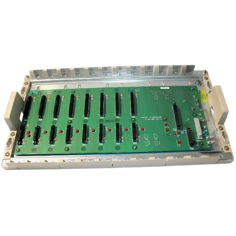 ABB 07BT62R1 GJV3074303R1 8-Slot Basic Module Rack Installation Guide
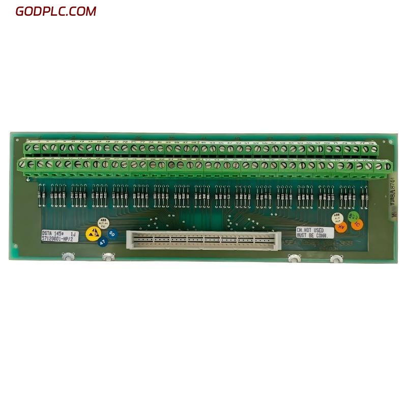 ABB DSTA 145 57120001-HP Analog Circuit Board Connection Unit Installation Guide
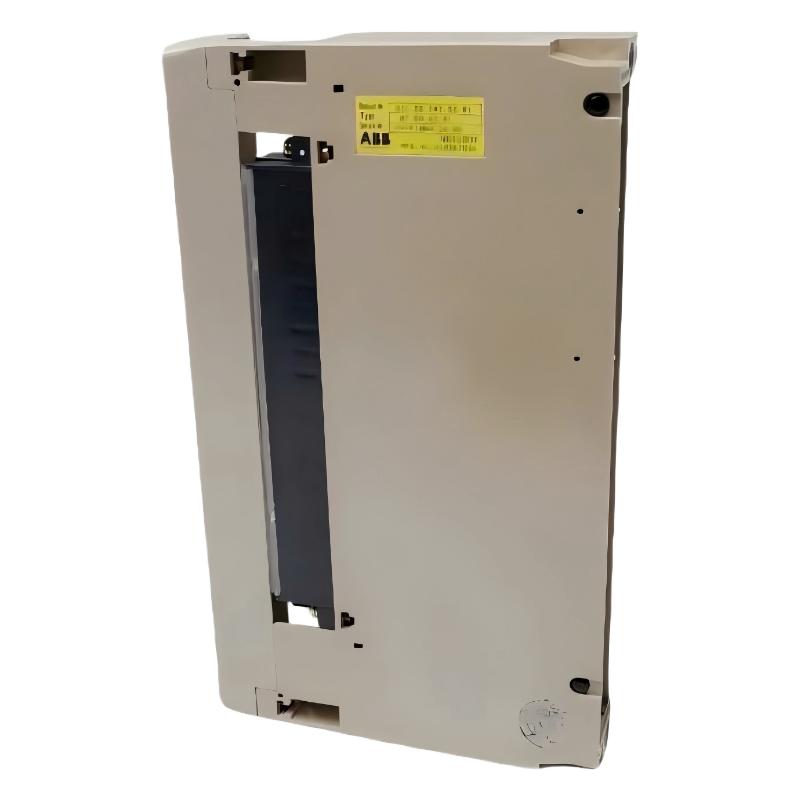 ABB 07 EA 63 R1 GJV3074353R1 Analog Input Module Installation Guide