100% Original, Ready to Ship!

ABB DSTA 145 57120001-HP Analog Circuit Board Connection Unit Installation Guide
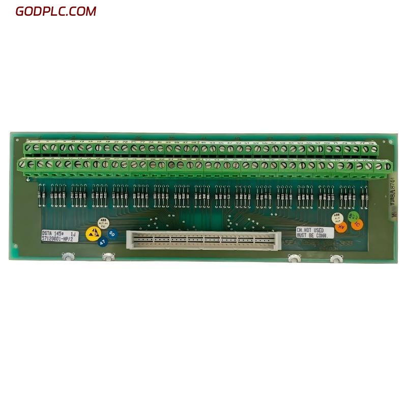
ABB DSTA 145 57120001-HP connection unit is widely used in ABB Advant/OCS analog input architectures to interface PT100 3-wire temperature signals. Installation faults are usually not caused by the module itself but by wiring integrity, shielding, and grounding errors rather than hardware failure in field applications.
In one commissioning case on a paper mill DCS system, we found that unstable temperature readings were traced back to incorrect terminal mapping rather than defective ABB DSTA 145 hardware. After rewiring and correcting shield grounding, signal stability improved immediately.
ABB DSTA 145 Connection Unit Technical Role in Analog System
The DSTA 145 acts as an analog signal termination and distribution interface between field sensors and the control system I/O module. It supports up to 31 PT100 3-wire inputs, ensuring stable signal routing and reducing noise interference in long-distance wiring.
- Function: Analog signal connection unit
- Supported signals: PT100 3-wire temperature inputs
- System integration: ABB Advant / 800xA legacy DCS systems
ABB DSTA 145 Installation Preparation and Safety Checks
Before installation, technicians should verify cabinet grounding and signal cable shielding conditions. In field engineering, we often observe that 70% of installation issues come from poor grounding instead of device defects.
- Confirm cabinet earth resistance < 1Ω
- Check shield continuity along entire cable path
- Verify correct terminal numbering before power-up
In one refinery site, improper shield termination caused a 2–3°C drift in PT100 readings across multiple channels.
ABB DSTA 145 Wiring and System Configuration (System Configuration Step)
During wiring, each PT100 3-wire sensor must be connected with correct compensation lead mapping. Incorrect swapping of compensation lines is a common fault source.
Typical wiring logic check:
CH1 = A / B / B-comp
CH2 = A / B / B-comp
Verify loop continuity with multimeter before energizing system
Ensure the connection unit is properly seated on the backplane or terminal rail depending on cabinet design. Loose mounting can cause intermittent signal dropout.
ABB DSTA 145 Commissioning and Signal Validation
After wiring, perform cold commissioning using system diagnostics tools. Monitor each channel for stable resistance values corresponding to ambient temperature.
We observed in a chemical plant commissioning that channel noise was present only during motor startup. After adjusting cable routing away from VFD power lines, signal fluctuation dropped from ±1.8°C to ±0.3°C.
- Check real-time analog input stability
- Validate all 31 channels sequentially
- Perform thermal simulation test if available
ABB DSTA 145 Installation Risks and Field Engineering Notes
Electromagnetic interference (EMI) is the most common hidden risk. Running analog signal cables parallel to high-power cables should be avoided whenever possible.
Another issue observed in maintenance practice is oxidation at terminal points, especially in humid environments. This leads to intermittent high resistance readings and false temperature spikes.
FAQ: Why does ABB DSTA 145 show unstable readings after installation?
Unstable readings are typically caused by grounding loops, incorrect PT100 wiring, or nearby power cable interference rather than module failure.
FAQ: Can ABB DSTA 145 be replaced without system shutdown?
In most Advant/DCS configurations, replacement requires system shutdown or I/O isolation to avoid signal corruption and unexpected process behavior.
FAQ: What is the most important installation rule?
Maintain strict separation between analog signal wiring and power circuits, and ensure consistent shield grounding at one end only.
Conclusion: ABB DSTA 145 Installation Engineering Summary
ABB DSTA 145 57120001-HP installation success depends on correct wiring discipline, grounding strategy, and EMI control rather than mechanical installation alone. Field experience shows that most “module faults” are actually system-level configuration or wiring issues.
Proper Installation Guide execution, combined with structured Setup / Commissioning validation and Fault Diagnosis practices, ensures long-term stable operation of the analog measurement system.
 ABB 085221-001 End Plate Installation Guide
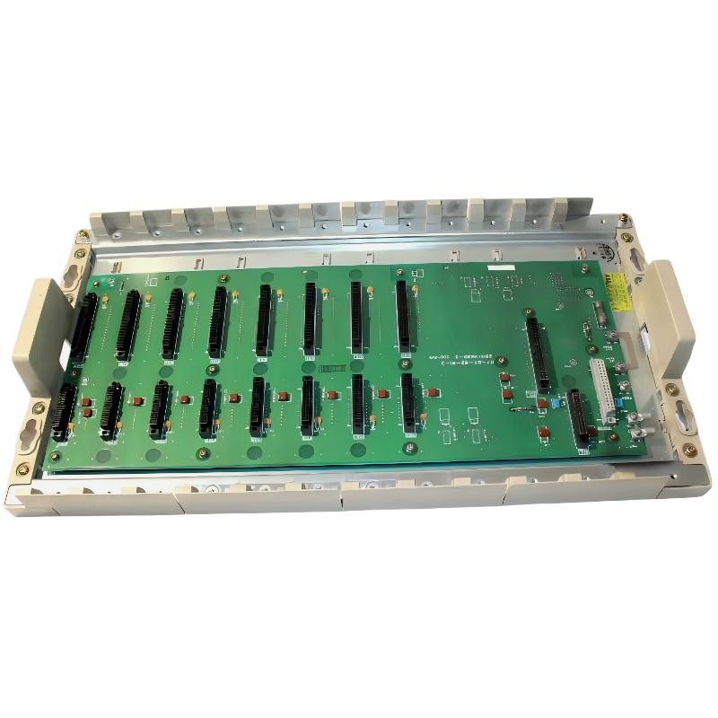 ABB 07BT62R1 GJV3074303R1 8-Slot Basic Module Rack Installation Guide
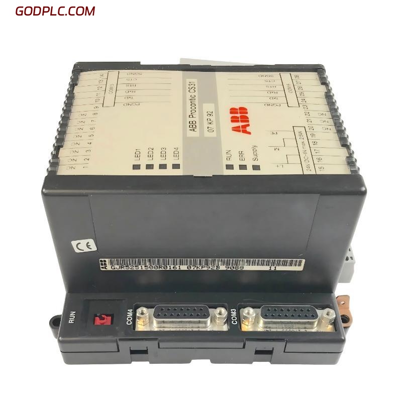 ABB 07 KP 92 GJR5251500R0161 Controller Installation Guide
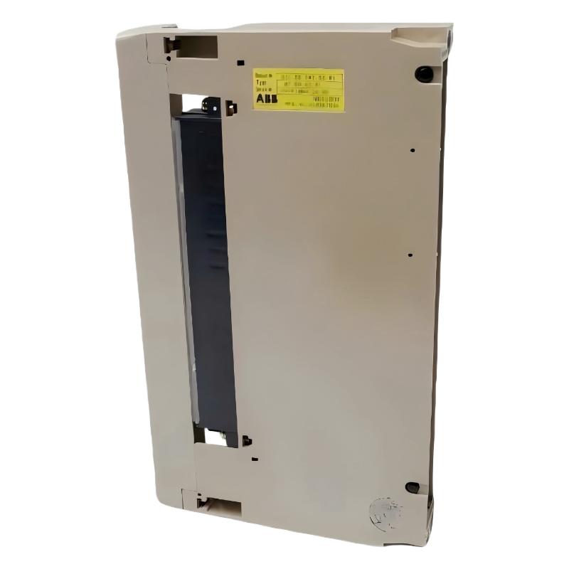 ABB 07 EA 63 R1 GJV3074353R1 Analog Input Module Installation Guide