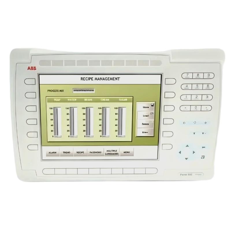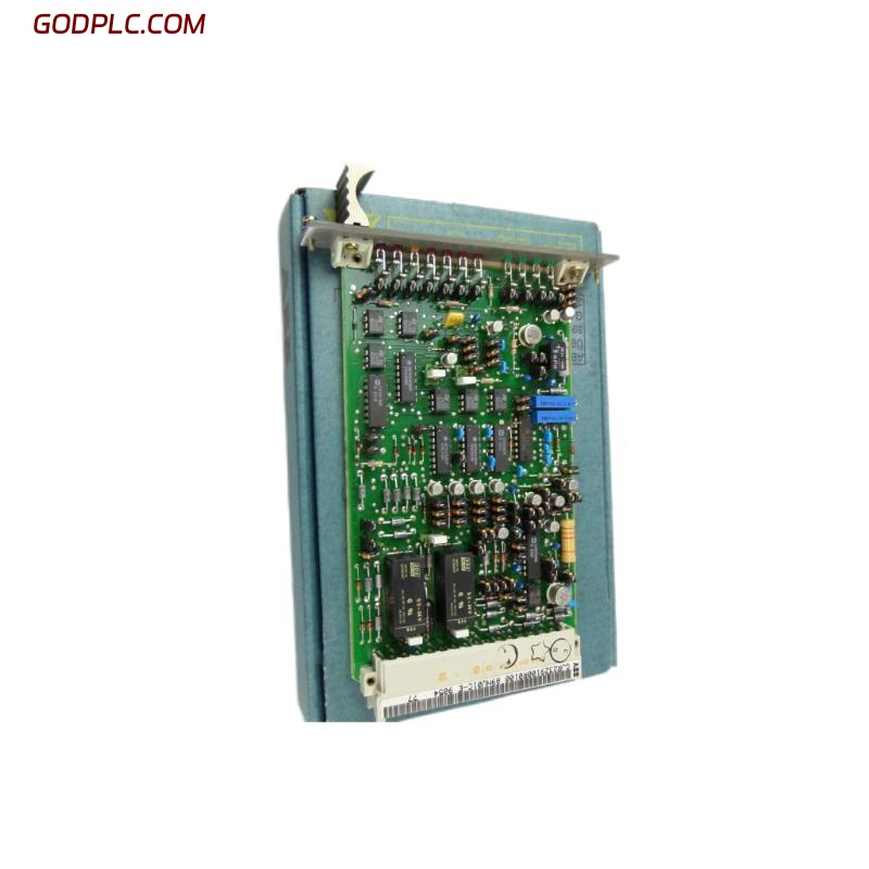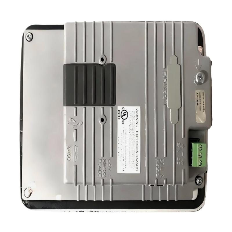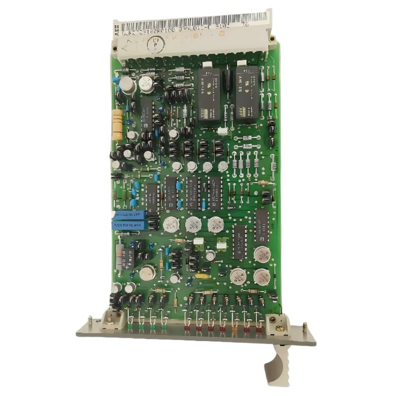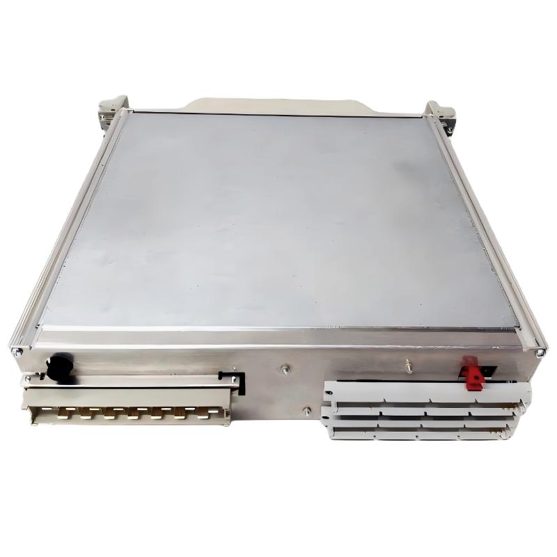
ABB 216NG63 Auxiliary Power Module Installation Overview
ABB 216NG63 HESG216877/K installation should begin with power-path verification, terminal identification, grounding inspection, and system configuration rather than simply mounting the module and applying power. In industrial control cabinets, an auxiliary power module is often blamed for unstable controller operation when the actual cause is upstream voltage drop, poor grounding, loose terminals, or an incorrectly configured power path.
The 216NG63 is associated with ABB industrial control and power-system hardware, and available product references identify the HESG216877 family with auxiliary power functions. Because legacy ABB assemblies can exist with different suffixes and revisions, the exact nameplate, cabinet drawing, terminal designation, and replacement documentation should always take precedence over assumptions based only on the model number.
ABB 216NG63 Installation Preparation and System Configuration
Before starting the Installation Guide procedure, establish exactly where the 216NG63 sits in the cabinet power architecture. The objective is to understand which circuits provide input power and which control electronics depend on its output.
- Confirm the complete identification: 216NG63 and HESG216877/K.
- Check the cabinet schematic against the actual wiring.
- Verify the upstream supply rating and protective device.
- Inspect terminal blocks for oxidation, looseness, or heat discoloration.
- Confirm protective earth and cabinet bonding.
- Check whether the module is part of a redundant or single-supply architecture.
- Record existing voltage measurements before replacing any component.
For older ABB systems, this preparation is particularly important. A replacement module should not be installed simply because its external appearance matches the removed unit. Revision markings, connector arrangement, and cabinet documentation should be checked first.
ABB 216NG63 Electrical Checks Before Setup
Power should remain isolated while mechanical and wiring checks are performed. Once the circuit is safe to energize, measure the supply at the actual module terminals rather than relying only on the upstream distribution point.
Field verification:
1. Isolate supply
2. Inspect terminals and connectors
3. Verify PE continuity
4. Energize according to site procedure
5. Measure input voltage at module terminals
6. Measure downstream auxiliary supply
7. Compare readings with the approved ABB system documentation
8. Record voltage under both no-load and operating conditions
A practical commissioning rule is to measure at three points: the cabinet supply, the 216NG63 input terminals, and the downstream control circuit. If the first measurement is stable but the second is low, the problem is normally in the wiring, protection, terminal block, or isolation path rather than in the auxiliary module itself.
ABB 216NG63 Wiring and Grounding Inspection
Wiring quality directly affects the stability of auxiliary power. Keep power conductors physically separated from high-current switching conductors where the cabinet design permits. Pay particular attention to shared returns and grounding arrangements.
- Use the approved terminal assignment from the system drawing.
- Verify polarity wherever DC connections are involved.
- Do not assume that visually similar terminals have identical electrical functions.
- Check that protective earth connections are mechanically secure.
- Inspect crimp terminals for signs of overheating or mechanical damage.
- Keep sensitive control wiring away from high-energy switching paths where practical.
Do not determine wiring correctness from wire color alone. In retrofit cabinets, wiring colors may reflect the original installation standard rather than the current plant standard.
ABB 216NG63 Setup and Commissioning Strategy
The commissioning objective is not simply to confirm that the module powers up. The important question is whether the auxiliary supply remains stable while the connected PLC Controller, Module, relay logic, or other control electronics transition into normal operation.
- Confirm the mechanical installation and connector seating.
- Apply power under the approved plant commissioning procedure.
- Check the auxiliary output at startup.
- Observe connected control equipment for abnormal resets or alarms.
- Measure voltage again after the downstream equipment is energized.
- Check for excessive temperature rise or unusual acoustic/electrical behavior.
- Document the measured values and final System Configuration.
Do not immediately connect every downstream load if the cabinet has been extensively modified. Energizing sections progressively makes it easier to identify a load that causes voltage collapse or excessive current demand.
ABB 216NG63 Commissioning Field Case and Engineering Judgment
In a representative field commissioning investigation involving an ABB auxiliary power circuit, the control system repeatedly restarted during cabinet startup. The initial suspicion was a defective power module because the controller lost power whenever several downstream circuits became active.
The engineer first measured the cabinet supply with the system unloaded and obtained a stable reading. A second measurement was taken directly at the auxiliary power input while the control cabinet was energized. The difference between the two points indicated a wiring-side voltage drop. Terminal inspection then found a high-resistance connection at the supply distribution point.
After the connection was corrected and the terminal assembly was rechecked, the auxiliary voltage remained stable during startup. The important Fault Diagnosis lesson is that the module should not be condemned until the input, output, grounding, and load behavior have been measured independently.
ABB 216NG63 Installation Validation and System Configuration
Final validation should include both electrical measurements and functional behavior. A module that produces the expected voltage without load may still fail when the connected controller and auxiliary circuits demand current.
- Record input voltage during normal operation.
- Record downstream auxiliary voltage during startup.
- Check controller or system reset behavior.
- Verify alarms and diagnostic indications.
- Inspect terminals after the initial operating period.
- Confirm that the final wiring matches the approved drawing.
For maintenance records, include the module identification, measured values, wiring changes, commissioning date, and any observed abnormal conditions. This makes later Troubleshooting substantially faster.
ABB 216NG63 Installation Guide FAQ
What should be checked before installing the ABB 216NG63?
Verify the complete part identification, cabinet drawing, supply path, terminal assignment, grounding, protective devices, and downstream load requirements before energizing the module.
Can the ABB 216NG63 be commissioned without checking the cabinet wiring?
No. Wiring errors, poor terminals, incorrect polarity, and inadequate grounding can create symptoms that resemble module failure. Wiring should be verified before hardware replacement is considered.
Why should voltage be measured directly at the module terminals?
The voltage at the distribution point can be normal while the voltage at the module is low because of cable resistance, loose terminals, damaged protection devices, or a high-resistance connection.
What is the most useful commissioning measurement?
Compare the supply voltage at the source, the 216NG63 input, and the downstream auxiliary circuit under both unloaded and operating conditions. The comparison helps locate voltage-drop problems.
Should downstream equipment be connected immediately after installation?
Where the plant procedure permits staged commissioning, progressive energization is preferable. It makes it easier to identify a downstream load that causes abnormal current demand or supply instability.
How should the 216NG63 System Configuration be documented?
Record the module identification, terminal wiring, supply path, connected loads, measured voltages, grounding arrangement, alarms, and final commissioning results in the maintenance documentation.
ABB 216NG63 Installation and Commissioning General Overview
A reliable ABB 216NG63 installation depends on understanding the complete auxiliary power path rather than treating the module as an isolated component. Correct wiring, grounding, supply verification, staged Setup, and loaded-voltage measurements provide the strongest basis for successful Commissioning. When these checks are documented, future Troubleshooting and Fault Diagnosis become considerably more efficient.