Table of Contents
- ABB 35EK91 GJR5143200R0001 Bus Coupler Unit Installation Overview
- ABB 35EK91 Bus Coupler Unit Preparation Before Setup
- ABB 35EK91 PLC System Wiring and Configuration
- ABB 35EK91 Commissioning and Functional Validation
- ABB 35EK91 Installation Guide FAQ
- General Overview
ABB 35EK91 GJR5143200R0001 Bus Coupler Unit Installation Overview
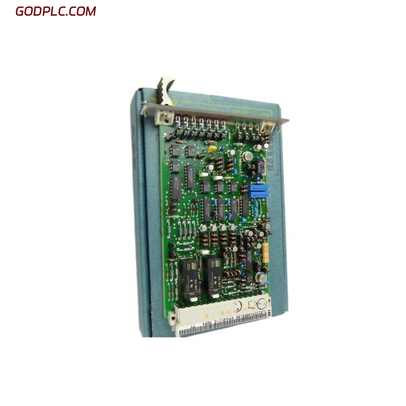
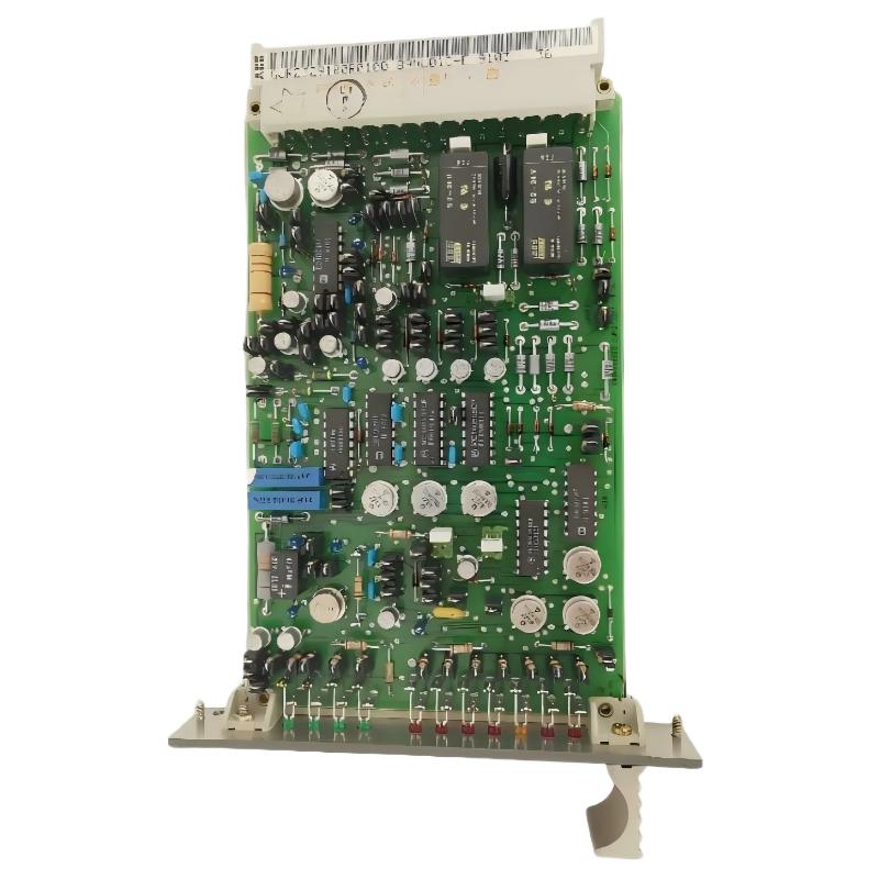
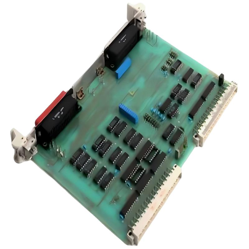
ABB 35EK91 GJR5143200R0001 Bus Coupler Unit installation problems are usually related to incorrect bus wiring, improper system configuration, or communication parameter mismatch rather than hardware failure. This Bus Coupler Unit is designed for industrial automation applications where reliable data exchange between PLC Controller networks and distributed modules is required.
The ABB 35EK91 Bus Coupler Unit acts as a communication bridge inside ABB Procontic automation systems. During an Installation Guide process, engineers must verify power supply quality, bus topology, addressing, and PLC communication settings before commissioning.
ABB 35EK91 Bus Coupler Unit Preparation Before Setup
Before installing the ABB 35EK91 GJR5143200R0001 Module, field engineers normally perform a System Configuration review. The purpose is to confirm that the existing PLC Controller architecture matches the Bus Coupler Unit requirements.
- Check PLC rack compatibility and communication architecture.
- Verify 24VDC power stability before connecting the module.
- Inspect bus cables for shielding and grounding conditions.
- Confirm node address allocation in the automation network.
- Record previous operating parameters before replacement.
In one commissioning case, an ABB 35EK91 replacement was installed in a production line where the controller showed unstable communication. Before power-up, the engineer measured the supply voltage at 24.1VDC and confirmed stable grounding resistance below the acceptable industrial range. This prevented unnecessary troubleshooting after startup.
ABB 35EK91 PLC System Wiring and Configuration
Correct wiring is the foundation of ABB 35EK91 Setup and Commissioning. A Bus Coupler Unit failure caused by reversed communication wiring can appear identical to a damaged communication board.
- Connect the power terminals according to the approved cabinet drawings.
- Maintain separation between communication cables and high-voltage cables.
- Connect shield grounding at the recommended control cabinet point.
- Verify communication cable continuity before system startup.
Typical pre-check command logic used during PLC diagnostics:
CHECK NODE STATUS
READ BUS COMMUNICATION VALUE
VERIFY MODULE ADDRESS
COMPARE PLC CONFIGURATION WITH FIELD DEVICE
During ABB 35EK91 Module installation, engineers should avoid changing multiple parameters simultaneously. A controlled modification process helps identify whether the issue originates from wiring, configuration, or the Bus Coupler Unit itself.
ABB 35EK91 Commissioning and Functional Validation
The ABB 35EK91 GJR5143200R0001 Commissioning procedure should include communication verification, signal exchange testing, and long-term monitoring.
- Power on the PLC Controller system.
- Check Bus Coupler Unit status indicators.
- Confirm communication between controller and remote modules.
- Monitor data transmission stability during operation.
- Save the final System Configuration parameters.
Field experience shows that many communication issues appear after several minutes of operation. Engineers should monitor the network load and error counters instead of checking only the initial startup condition.
ABB 35EK91 Installation Guide FAQ
What is the main function of ABB 35EK91 GJR5143200R0001 Bus Coupler Unit?
The ABB 35EK91 Bus Coupler Unit provides communication connection between different automation sections, allowing PLC Controller systems and distributed modules to exchange process data.
Why does ABB 35EK91 fail during initial commissioning?
Most first-time commissioning failures are caused by incorrect addressing, communication cable problems, or mismatch between PLC configuration and actual hardware installation.
How can engineers verify ABB 35EK91 communication status?
Engineers can check PLC diagnostic information, module status indicators, communication counters, and network signal quality during Fault Diagnosis.
General Overview
ABB 35EK91 GJR5143200R0001 Bus Coupler Unit installation requires more than physical mounting. Successful Setup and Commissioning depends on correct wiring practices, accurate System Configuration, and practical field validation. A structured Installation Guide approach reduces downtime and improves long-term PLC network reliability.