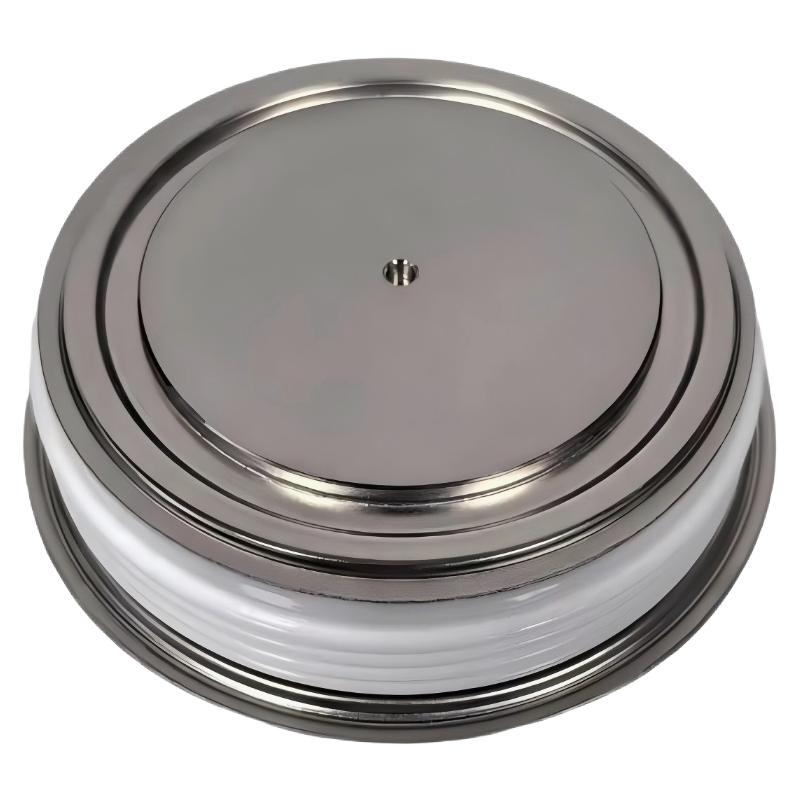
ABB 5SDF0860H0003 Diode Installation Guide Overview
ABB 5SDF0860H0003 installation requires more attention to mechanical contact, polarity, cooling, and electrical isolation than a conventional low-voltage diode installation. The device is identified as ABB product ID 3BHL000397P0001, with a 68 mm package and 6 kV voltage class, and is used in high-power drive and power-conversion equipment. ABB documentation listings associate this diode with medium-voltage drive applications including ACS1000 and ACS5000 systems.
The most important point during commissioning is not simply installing the diode in the correct position. The engineer must confirm the complete mechanical and electrical environment before energization, because uneven mounting pressure, poor thermal contact, contamination, or incorrect polarity can create abnormal heating and electrical stress.
ABB 5SDF0860H0003 Diode Specifications for Installation
- ABB Type Designation: 5SDF0860H0003
- Product ID: 3BHL000397P0001
- Component type: high-power diode
- Package diameter: approximately 68 mm
- Voltage class: 6 kV
- Typical application area: medium-voltage drive and power-conversion equipment
- Related ABB drive platforms: ACS1000 and ACS5000 applications
ABB 5SDF0860H0003 Installation Preparation and System Configuration
Before starting the Installation Guide procedure, isolate the power-conversion cabinet and follow the site’s high-voltage safety procedure. Do not treat the 5SDF0860H0003 as a simple plug-in Module. It is part of a high-energy semiconductor power circuit, so the surrounding mechanical stack, heat-transfer arrangement, electrical clearances, and protection circuit must all be checked.
ABB 5SDF0860H0003 Diode Physical Inspection
Inspect the diode before installation. Check the ceramic body, contact surfaces, markings, and mechanical condition. A damaged contact surface can produce higher local resistance and consequently higher semiconductor temperature during operation.
- Check for cracks or visible mechanical damage.
- Verify the complete ABB part number.
- Compare polarity and orientation with the original installation.
- Clean mating surfaces according to the equipment manufacturer’s maintenance procedure.
- Confirm that the cooling assembly is free from contamination.
ABB 5SDF0860H0003 Diode Mechanical Mounting
Mechanical mounting is one of the most important parts of this Setup procedure. A press-pack style power semiconductor depends on controlled mechanical contact. The replacement diode should not be installed by simply tightening hardware until it feels mechanically secure.
Use the mounting arrangement and specified force or torque values from the applicable ABB equipment documentation. The exact mechanical requirement depends on the heatsink and stack design. Excessive pressure can damage the semiconductor package, while insufficient pressure can increase contact resistance and thermal impedance.
- Verify the mechanical stack configuration.
- Position the diode according to the original polarity.
- Ensure both electrical contact surfaces are correctly seated.
- Apply the specified mounting force using calibrated tooling.
- Confirm that the assembly remains mechanically stable after tightening.
ABB 5SDF0860H0003 Electrical Checks Before Commissioning
Electrical verification should be performed before the drive is returned to service. A resistance measurement alone is not sufficient to prove that a high-voltage diode is healthy, but it can help identify an obvious short circuit or abnormal connection.
Power isolated
↓
Verify discharge and zero-energy condition
↓
Check diode polarity
↓
Inspect mechanical contact
↓
Check circuit continuity
↓
Compare semiconductor readings with the approved maintenance procedure
↓
Verify protection and cooling system
↓
Proceed to controlled commissioning
ABB 5SDF0860H0003 Diode Polarity Verification
Polarity must be checked against the circuit drawing rather than assumed from physical orientation. When replacing a failed diode, photograph the original assembly and record the orientation before removing the old component. This simple field practice prevents a surprisingly common commissioning error.
ABB 5SDF0860H0003 Setup and Commissioning Validation
During commissioning, begin with the lowest practical energy condition permitted by the equipment procedure. Monitor the converter or drive for abnormal current distribution, temperature rise, unexpected alarms, and cooling-system performance.
In a typical replacement investigation, an engineer may find that the new diode passes an electrical inspection but the semiconductor temperature rises faster than neighboring devices after energization. Instead of immediately replacing the diode again, the correct troubleshooting approach is to inspect the contact pressure, heatsink condition, cooling flow, polarity, and current sharing. This diagnostic sequence separates a component fault from an installation fault.
ABB 5SDF0860H0003 Commissioning Validation Checklist
- Correct 5SDF0860H0003 part number confirmed.
- 3BHL000397P0001 identification verified.
- Correct polarity confirmed against the circuit diagram.
- Mechanical mounting completed according to approved equipment documentation.
- Cooling surfaces and cooling system inspected.
- Electrical connections checked.
- No abnormal converter alarm appears during controlled startup.
- Temperature behavior is consistent with the surrounding semiconductor devices.
ABB 5SDF0860H0003 Installation Troubleshooting Points
If the drive immediately reports a converter fault after replacement, do not assume that the new diode is defective. Fault Diagnosis should begin by checking whether the fault is associated with the replaced branch, gate/control circuitry where applicable, current measurement, cooling, or another semiconductor in the same power stage.
ABB 5SDF0860H0003 Installation Questions
What is the ABB 5SDF0860H0003 component?
It is an ABB high-power diode identified by product ID 3BHL000397P0001. The catalog designation identifies it as a 68MM/6kV diode.
Can the ABB 5SDF0860H0003 be installed like a standard PCB diode?
No. Its high-power application requires appropriate mechanical mounting, electrical isolation, cooling, polarity verification, and high-voltage safety procedures.
What should be checked before ABB 5SDF0860H0003 commissioning?
Verify the part number, polarity, mechanical contact, cooling arrangement, electrical connections, protection circuit, and the applicable drive System Configuration.
ABB 5SDF0860H0003 Installation Guide General Conclusion
The ABB 5SDF0860H0003 Installation Guide should be treated as a complete power-stage installation procedure rather than a simple component replacement task. Correct identification, controlled mechanical mounting, polarity verification, thermal inspection, and gradual Setup and Commissioning provide the foundation for reliable operation. When a problem appears after replacement, systematic Troubleshooting and Fault Diagnosis are more effective than immediately assuming semiconductor failure.