
ABB 70EI05A-E HESG447427R1 Input Module Installation Guide
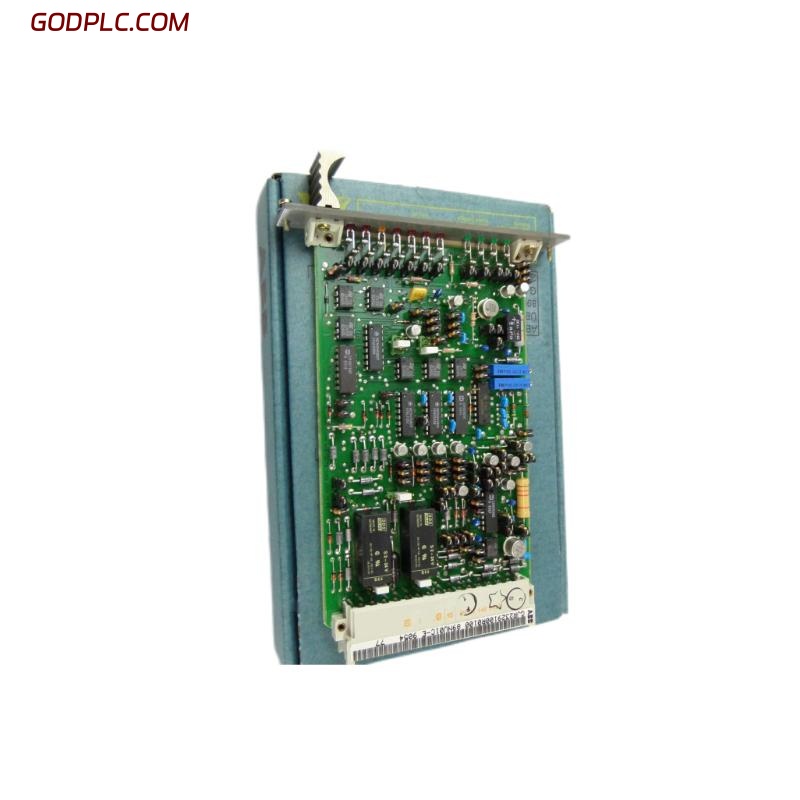
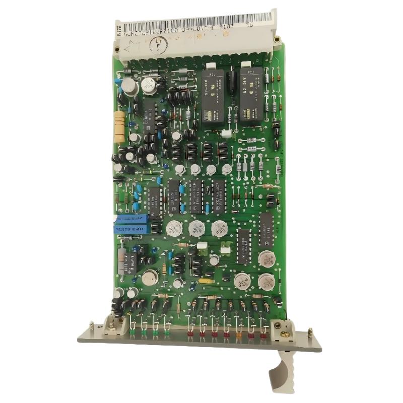
Installing the ABB 70EI05A-E HESG447427R1 correctly starts with identifying the module as a dedicated speed sensor input device for ABB Procontrol systems. The module is used to acquire pulse or frequency signals from rotating equipment and transfer the processed speed information into the control system. Before commissioning, the field sensor type, rack position, signal wiring, grounding, and System Configuration should all be verified rather than assuming that an existing replacement card can simply be plugged in.
ABB 70EI05A-E HESG447427R1 Input Module Role
The ABB 70EI05A-E HESG447427R1 is associated with the Procontrol P13/P14 family and is commonly identified as a speed sensor input module. Its job is not simply to detect an ON/OFF condition. The input stage handles pulse or frequency information from a speed sensor, making correct signal characteristics important during installation and Setup.
Typical applications include rotating machinery speed monitoring, turbine instrumentation, pulse acquisition, and protection-related measurement circuits. The exact sensor arrangement must be checked against the plant engineering documentation before energizing the channel.
ABB 70EI05A-E HESG447427R1 Installation Preparation
A reliable Installation Guide should begin with the signal chain, not the card itself. Confirm the relationship between the sensor, field cable, terminal interface, ABB 70EI05A-E module, rack, and controller.
- Verify the complete 70EI05A-E model and HESG447427R1 part number.
- Check the assigned rack and slot against the approved System Configuration.
- Identify whether the field device is a magnetic pickup, Hall-effect sensor, encoder, or another pulse source.
- Inspect cable shielding, termination, grounding, and cable routing.
- Compare the expected pulse amplitude and frequency with the project signal specification.
- Confirm that the replacement module is electrically and functionally suitable before insertion.
For legacy Procontrol installations, documentation quality can vary considerably. A useful field practice is to photograph the existing wiring and record the original rack position before removing a card.
ABB 70EI05A-E HESG447427R1 Speed Sensor Wiring
Speed measurement problems are frequently caused by the signal path rather than the input module. A sensor that produces a clean waveform at the machine can still deliver a degraded signal at the rack because of cable resistance, shielding problems, moisture, electromagnetic interference, or incorrect termination.
- Isolate the equipment according to the plant electrical procedure.
- Verify field cable identification against the wiring drawing.
- Check signal polarity where the sensor circuit requires it.
- Inspect shield termination and separation from high-current cables.
- Measure the field signal before connecting it to the input channel.
- Confirm continuity and insulation condition of the cable.
Do not use a generic PLC wiring assumption for a dedicated speed input. The sensor output characteristics and the Procontrol channel specification should determine the final connection method.
ABB 70EI05A-E HESG447427R1 System Configuration
The System Configuration should define the input channel, associated controller logic, scaling or frequency interpretation, and alarm or protection functions. If the module is replacing an existing unit, compare the new installation against the configuration of the removed card rather than creating an unverified configuration from scratch.
For rotating equipment, the relationship between pulse frequency and shaft speed also depends on the number of pulses generated per revolution. This value must match the actual mechanical sensing arrangement. A wrong pulse-per-revolution setting can produce a perfectly stable but completely incorrect speed indication.
ABB 70EI05A-E Setup and Commissioning Checks
During Setup and Commissioning, start with a static signal check before running the machine. Verify that the control system recognizes the expected input condition and that the channel does not generate unexplained pulses while the shaft is stationary.
# Pseudo diagnostic sequence
CHECK MODULE_ID
CHECK RACK_SLOT
CHECK CHANNEL_STATUS
CHECK SENSOR_SIGNAL
CHECK SHIELD_GROUND
CHECK PULSE_FREQUENCY
COMPARE SPEED_WITH_REFERENCE
After the static check, rotate the equipment under controlled conditions. Compare the displayed speed with an independent reference. A difference that remains proportional throughout the operating range generally points toward configuration or scaling, while intermittent changes are more likely to require investigation of the sensor, cable, grounding, or input signal quality.
ABB 70EI05A-E Input Module Signal Validation
Signal validation should include more than checking whether an LED changes state. Where permitted by the plant procedure, use suitable test instrumentation to observe the pulse waveform and compare it with the expected operating condition.
- Check pulse presence at the sensor.
- Check pulse integrity at the cabinet termination.
- Compare measured frequency with calculated shaft speed.
- Observe the signal during acceleration and deceleration.
- Check for false pulses when nearby high-power equipment switches.
A practical commissioning record should include the machine speed, measured frequency, sensor condition, alarm status, and final control-system indication.
ABB 70EI05A-E HESG447427R1 Field Commissioning Case
In one commissioning investigation involving a legacy Procontrol speed channel, the initial indication was unstable even though the replacement input module had been installed correctly. The engineering team did not immediately classify the ABB 70EI05A-E as defective. Instead, the signal was checked at successive points in the circuit.
The sensor output was present at the machine, but the waveform at the cabinet was noticeably less stable. Cable routing was then inspected and the signal cable was found running close to a high-current motor cable. After correcting the routing and restoring the intended shielding arrangement, the speed indication became stable during acceleration testing.
The important commissioning lesson was that replacing an Input Module without validating the complete sensor-to-controller signal path would not have addressed the actual installation problem.
ABB 70EI05A-E HESG447427R1 Installation FAQ
What type of signal is normally associated with the ABB 70EI05A-E HESG447427R1?
The module is commonly used for pulse or frequency signals from speed-sensing devices in ABB Procontrol applications. The exact electrical interface should always be confirmed against the project documentation for the installed system.
Can the ABB 70EI05A-E be installed in any Procontrol rack slot?
No. The assigned rack and slot should be verified from the system engineering documentation because module location and configuration are part of the control-system architecture.
Why should the sensor cable be checked before commissioning?
A damaged, poorly shielded, or incorrectly routed cable can distort a speed pulse before it reaches the input module. This can create symptoms that appear to be an Input Module problem.
What should be checked after replacing the input module?
Verify module identification, rack position, field wiring, sensor signal, System Configuration, displayed frequency or speed, and associated alarms before returning the equipment to normal operation.
Is a stable speed indication sufficient to complete commissioning?
No. The signal should also be checked during startup, acceleration, steady operation, and controlled deceleration where the operating procedure permits. Transient signal problems may not appear at constant speed.
Why is pulse-per-revolution information important?
The controller converts the measured pulse frequency into a speed value based on the sensing arrangement. An incorrect pulse-per-revolution value can therefore produce an incorrect speed even when the input signal itself is healthy.
ABB 70EI05A-E HESG447427R1 Installation Conclusion
The ABB 70EI05A-E HESG447427R1 Installation Guide should be treated as a complete signal-chain commissioning exercise rather than a simple card replacement procedure. Correct rack placement, sensor compatibility, wiring integrity, shielding, System Configuration, and independent signal validation are all important. For legacy ABB Procontrol equipment, disciplined measurement before and after installation is often the fastest way to distinguish a module issue from a field instrumentation problem.