
ABB 89AR30/R0100 Relay Unit Installation Guide
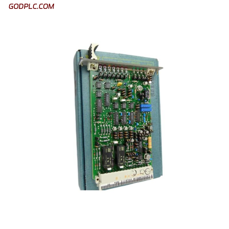
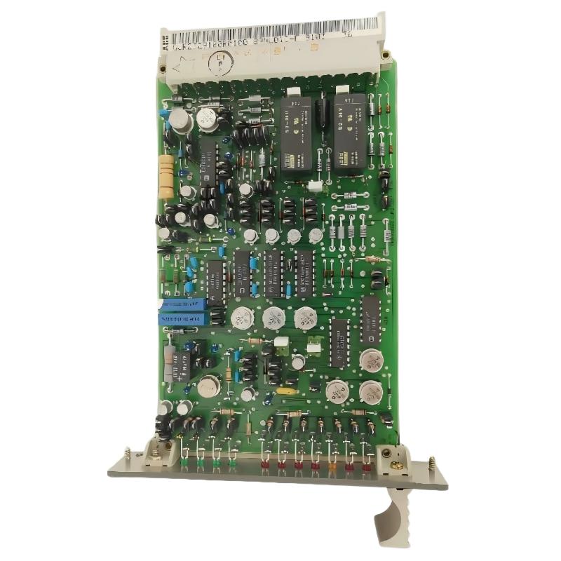
The ABB 89AR30/R0100 Relay Unit installation process should begin with model verification, rack compatibility checks, wiring inspection, and confirmation of the existing protection logic. Used in ABB Procontrol P turbine control applications, this relay unit is associated with control and protection functions where incorrect installation or contact wiring can affect system availability. A reliable Setup and Commissioning procedure must therefore verify both the physical installation and the response of the connected control circuits.
Table of Contents
- Relay Unit Role and System Configuration
- Pre-Installation Engineering Checks
- Mounting and Electrical Connections
- Setup and Commissioning Verification
- Field Commissioning Example
- Installation FAQ
- General Conclusion
ABB 89AR30/R0100 Relay Unit Role and System Configuration
The 89AR30/R0100 is identified in industrial equipment listings as an ABB relay unit associated with the Procontrol P turbine control system. Available product descriptions indicate a multi-relay arrangement intended for control and protection applications. Before assigning individual terminals or contact functions, engineers should confirm the exact hardware revision and the applicable circuit drawings.
In a typical relay-based control architecture, the controller generates a command, the relay unit switches the designated circuit, and downstream equipment responds to the resulting contact state. The actual logic, contact arrangement, and permitted loads must be established from the project documentation rather than inferred from the model number alone.
Pre-Installation Engineering Checks for ABB 89AR30/R0100
Preparation is particularly important when replacing a relay unit in an operating power-generation or process-control installation. A mechanically compatible component is not automatically electrically interchangeable.
- Verify the complete part number, including the R0100 suffix, against the equipment list and approved bill of materials.
- Compare the installed unit with the relevant rack layout, connector type, and terminal assignment drawings.
- Record existing wire numbers and contact assignments before disconnecting any conductors.
- Confirm the rated supply, control signal levels, contact ratings, and load requirements from approved documentation.
- Review the cause-and-effect matrix and identify any trip, permissive, or interlock functions affected by the replacement.
- Apply the plant’s isolation, lockout/tagout, and electrical safety procedures before handling the hardware.
ABB 89AR30/R0100 Mounting and Electrical Connections
Mount the relay unit only in the specified equipment position and use the approved connector and retention arrangement. Inspect the rack connector for bent contacts, contamination, corrosion, or mechanical damage. A poor connector interface can produce intermittent operation that resembles an internal relay failure.
- Confirm that the relevant circuits are safely isolated and that stored energy has been addressed.
- Inspect the replacement unit and compare its identification details with the approved configuration.
- Install the unit using the manufacturer’s specified mechanical procedure. Do not force a connector into position.
- Reconnect conductors according to the verified wiring schedule and check that each wire number matches its destination.
- Inspect protective grounding, segregation, cable routing, and connector retention where applicable to the assembly.
- Complete an independent wiring check before authorizing energization.
Do not assume that all relay contacts have identical functions. Where a protection design uses redundant channels or voting logic, the designated contact paths must remain consistent with the approved circuit design.
ABB 89AR30/R0100 Setup and Commissioning Verification
Commissioning should establish that the relay unit behaves correctly within the complete control loop. Testing an individual contact without verifying the initiating command and the downstream response may leave important system faults undetected.
- Static inspection: Confirm the hardware identity, mounting, connector engagement, and wiring records.
- Input verification: Measure the applicable supply or control signal using the approved test points and specified limits.
- Command verification: Confirm that the intended controller output changes state under the approved test condition.
- Contact verification: Check the relevant relay contact transition using an approved method and the correct circuit reference.
- Functional verification: Confirm the downstream indication or response without defeating protective interlocks.
- Documentation: Record measured values, test conditions, results, and any deviations from the acceptance criteria.
Commissioning record — illustrative pseudocode

VERIFY model_identity
VERIFY approved_wiring_revision
VERIFY supply_within_documented_limits
COMMAND approved_test_condition
CHECK expected_relay_contact_state
CHECK downstream_feedback
RECORD measured_values_and_result
RESTORE normal_operating_configuration
The commands above are a documentation aid, not executable ABB diagnostic commands. The actual test sequence and acceptable electrical values must come from the applicable equipment documentation and plant commissioning procedure.
ABB 89AR30/R0100 Field Commissioning Example
Consider a hypothetical replacement during a turbine-control maintenance outage. Following installation, the control system indicates that a relay-dependent permissive has not returned to its expected state. Replacing the unit again immediately would be premature.
The commissioning engineer first verifies that the controller output changes as expected. The next check compares the relay contact state with the approved wiring diagram. If the input command is correct but the contact state is not, the investigation moves toward the relay, connector interface, or contact circuit. If the contact state is correct but the permissive remains absent, attention shifts to downstream wiring, feedback logic, or the receiving input channel.
This example illustrates a practical diagnostic method, not a documented incident involving this exact model. Actual acceptance depends on measured results and the manufacturer’s specified limits.
ABB 89AR30/R0100 Relay Unit Installation FAQ
What should be verified before installing the ABB 89AR30/R0100?
Confirm the complete part number, hardware compatibility, connector arrangement, approved wiring diagrams, electrical ratings, and intended control function.
Can the relay unit be replaced while the control system is energized?
Do not assume that live replacement is permitted. Follow the equipment-specific instructions and site isolation policy. Protection-related circuits require particular care because an interruption can affect system availability or safety.
Does the 89AR30/R0100 require software configuration?
The required configuration depends on the installed Procontrol P architecture and the application. Verify controller logic, channel assignments, and associated settings against the approved project documentation instead of assuming that the relay unit has a standalone software setup procedure.
How can incorrect relay wiring be detected during commissioning?
Compare each conductor with the wiring schedule, verify the commanded contact transition, and confirm the downstream signal. Use approved test points and documented contact states.
What information should be included in the commissioning report?
Record the installed part number, equipment location, drawing revision, test conditions, measured electrical values, contact results, downstream response, deviations, and authorization for return to service.
General Conclusion for ABB 89AR30/R0100 Relay Unit Installation
A dependable ABB 89AR30/R0100 Relay Unit Installation Guide must address more than physical mounting. Model verification, circuit integrity, contact-state testing, System Configuration review, and controlled Setup and Commissioning are all necessary to establish reliable operation. Where exact terminal assignments or electrical ratings are unavailable, the approved ABB documentation and site drawings must take precedence over assumptions. This engineering-led approach reduces commissioning errors and provides a traceable basis for maintaining industrial control and protection systems.