 Table of Contents
- Overview of ABB 087627-001 Laser Driver Installation
- Preparation Before ABB 087627-001 Setup
- ABB 087627-001 Laser Driver Wiring and System Configuration
- ABB 087627-001 Commissioning and Signal Validation
- Real Field Case During ABB 087627-001 Installation
- ABB 087627-001 Laser Driver FAQ
- General Overview of ABB 087627-001 Laser Driver Application
ABB 087627-001 Laser Driver Installation Overview for Industrial Control Systems
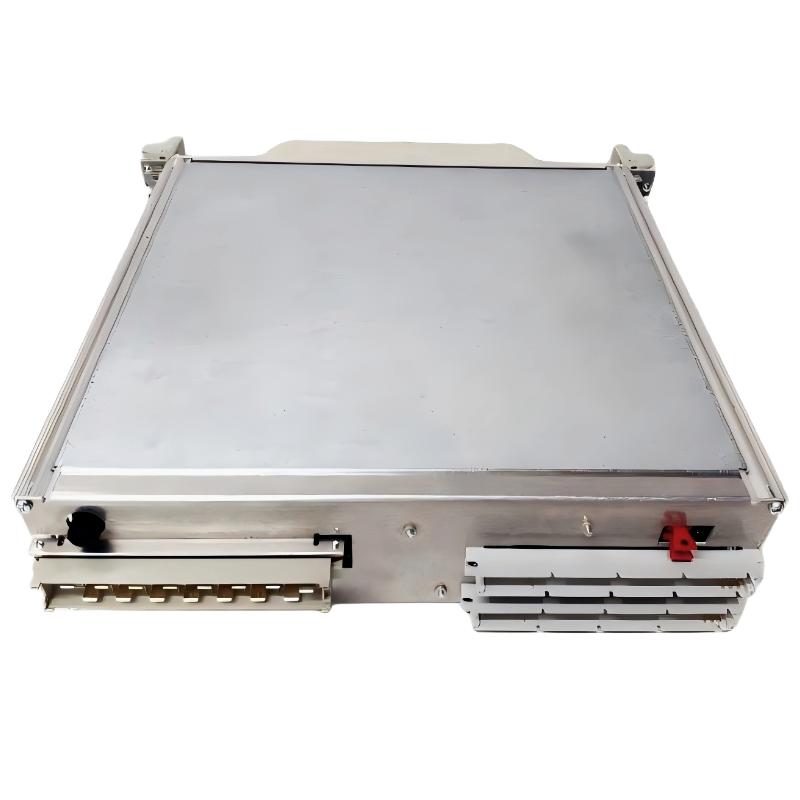
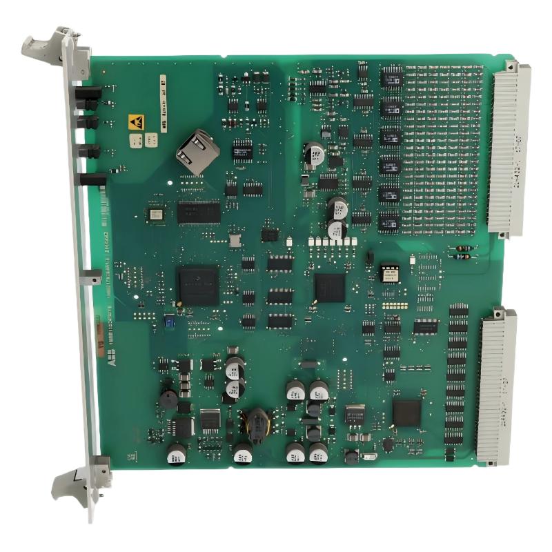
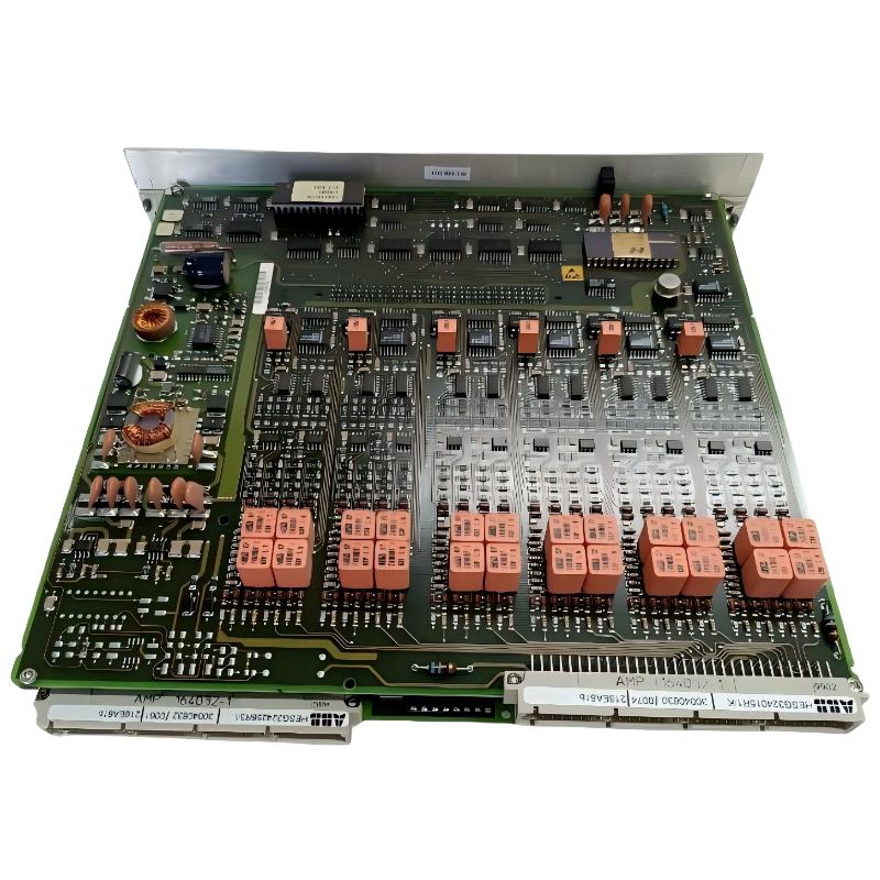
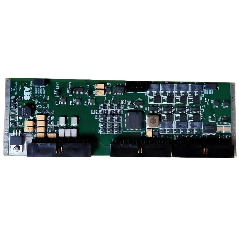
ABB 087627-001 Laser Driver installation requires correct electrical integration, optical alignment verification, and proper system configuration. In industrial automation applications, incorrect power supply stability or signal connection can cause unstable laser output even when the module itself is not damaged.
The ABB 087627-001 is applied as a laser control component within industrial control equipment and automation systems. During commissioning, engineers normally focus on output stability, driver response, communication feedback, and integration with the main PLC Controller or control platform.
Preparation Before ABB 087627-001 Laser Driver Setup and Commissioning
Before installing the ABB 087627-001 Laser Driver Module, the complete System Configuration should be reviewed. The technician should confirm the controller interface, power source condition, grounding method, and surrounding electromagnetic environment.
- Check DC power stability before connecting the laser driver.
- Verify connector pin assignment according to the system drawing.
- Inspect cable shielding and grounding points.
- Confirm compatibility with the existing PLC Controller or automation rack.
Field experience shows that many laser driver failures reported during startup are actually caused by unstable external conditions. A voltage fluctuation of only a few volts can affect laser control performance in precision applications.
ABB 087627-001 Laser Driver Wiring and System Configuration
The wiring process should follow industrial commissioning practice instead of simple module replacement. The ABB 087627-001 Laser Driver requires clean power input and reliable signal feedback paths.
- Disconnect system power before installation.
- Install the Laser Driver Module into the designated control position.
- Connect power supply terminals and verify polarity.
- Connect signal lines between the driver and control system.
- Inspect shielding connection to reduce electrical noise.
During installation, engineers usually measure the following values:
- Supply voltage stability
- Control signal level
- Output response feedback
- Ground potential difference
ABB 087627-001 Laser Driver Commissioning and Signal Validation
The commissioning stage is where the Installation Guide becomes a practical verification process. The engineer should not immediately increase operating parameters before confirming stable feedback signals.
Check Power Input:
Voltage = Rated DC Supply
Status = Normal

Check Driver Feedback:
Signal Response = Stable
Output Command = Follow PLC Reference

Verify System Configuration:
PLC Communication = OK
Laser Driver Feedback = Active
A proper commissioning sequence includes low-level output testing first, followed by gradual increase to normal operating conditions.
Real Field Case During ABB 087627-001 Laser Driver Installation
In one commissioning case, an ABB 087627-001 Laser Driver showed unstable output after replacement. The first inspection suggested possible hardware failure, but the engineering team measured the supply line and found a 2.8V fluctuation caused by a damaged power connection.
After repairing the power wiring and improving grounding, the laser output became stable and the feedback signal returned to normal operation. The troubleshooting process confirmed that installation quality directly affected driver performance.
ABB 087627-001 Laser Driver FAQ
What should be checked before ABB 087627-001 Laser Driver installation?
Before installation, verify power supply condition, connector wiring, grounding, and PLC Controller compatibility. Incorrect preparation may create false fault alarms.
Can ABB 087627-001 operate with existing automation systems?
Yes, when the System Configuration and interface requirements are correctly matched with the existing control architecture.
Why is signal feedback important during commissioning?
Feedback signals confirm whether the Laser Driver Module is responding correctly to control commands and help engineers identify wiring or configuration problems.
What tools are useful for ABB 087627-001 Fault Diagnosis?
Multimeters, oscilloscopes, PLC diagnostic software, and signal analyzers are commonly used during field troubleshooting.
How can electromagnetic interference affect the laser driver?
Strong electromagnetic interference may introduce unstable control signals and abnormal laser output. Proper shielding and grounding reduce these problems.
What is the recommended commissioning sequence?
Engineers normally verify power, communication, feedback signals, and output response step by step before full operation.
Is ABB 087627-001 replacement enough to solve all faults?
No. A complete Fault Diagnosis process should confirm whether the problem comes from the driver, wiring, controller, or external system.
Why should installation records be maintained?
Installation records help future engineers compare operating data and quickly identify abnormal changes.
General Overview of ABB 087627-001 Laser Driver Application
The ABB 087627-001 Laser Driver Installation Guide is not only about mounting the module but also about verifying electrical quality, control communication, and system performance. Practical commissioning experience shows that correct setup procedures greatly reduce unnecessary replacement and improve long-term reliability.