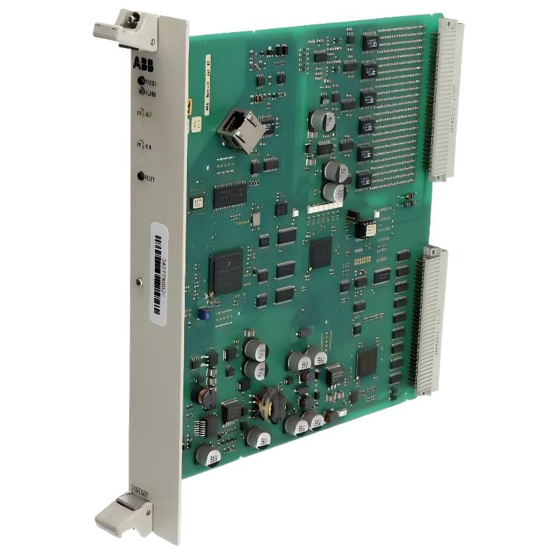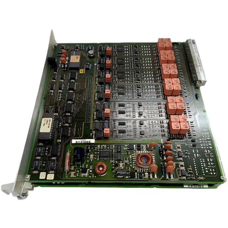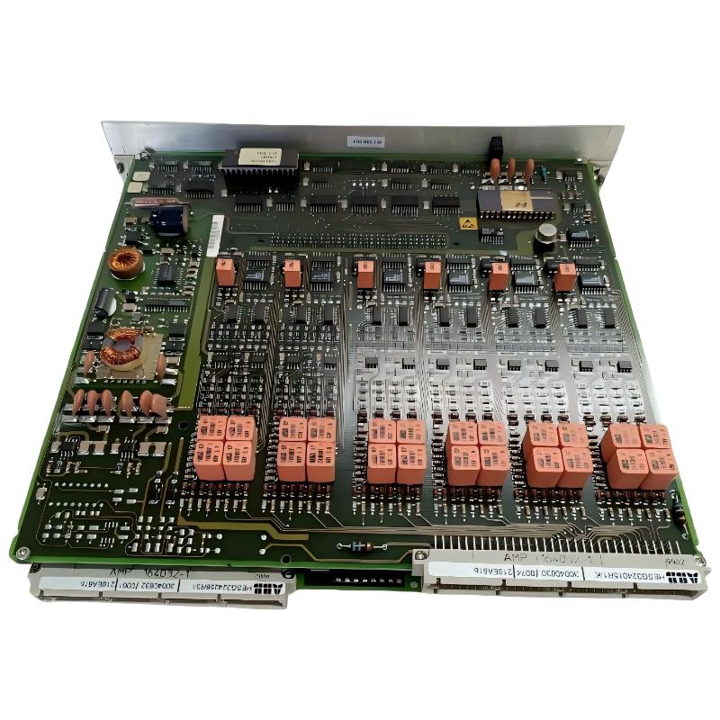
ABB 216NG63 Auxiliary Power Module Fault Diagnosis Overview
ABB 216NG63 HESG441635R1 Auxiliary Power Module faults are commonly related to unstable DC supply, poor connections, overload conditions, or incorrect system integration. Before replacing the PLC power module, engineers should complete a Troubleshooting process based on measured data and system behavior.
ABB 216NG63 Power Module Fault Symptoms Analysis
- Connected PLC or I/O modules restart unexpectedly.
- Auxiliary DC voltage fluctuates during operation.
- System alarms indicate power supply interruption.
- Communication modules lose connection after startup.
- Status indicators show abnormal operating conditions.
Common Causes of ABB 216NG63 Auxiliary Power Module Failure
- Loose terminal connections causing voltage drops.
- DC input instability from external battery systems.
- Grounding problems inside control cabinets.
- Overloaded auxiliary power distribution.
- Aging components inside the power module.
ABB 216NG63 Troubleshooting and Fault Diagnosis Process
The correct troubleshooting method starts from system symptoms and moves toward component-level verification. Replacing the module immediately can hide the real cause and increase maintenance cost.
- Review controller alarm history.
- Measure DC input voltage during operation.
- Check auxiliary output voltage stability.
- Inspect connectors and terminal blocks.
- Compare measurements with normal operating values.
Fault Diagnosis Procedure:

Step 1:
Measure DC Input Voltage

Step 2:
Measure Auxiliary Output Voltage

Step 3:
Check Load Current

Step 4:
Inspect Ground Reference

Step 5:
Verify System Recovery
ABB 216NG63 Auxiliary Power Module Real Field Troubleshooting Case
In one industrial control system troubleshooting case, an ABB 216NG63 Auxiliary Power Module was suspected after several I/O modules lost communication.
The first observation showed the controller voltage dropping from 24.2VDC to 22.6VDC during equipment startup. Engineers initially checked the power module output, but the module passed static testing.
Further inspection found a high-resistance connection at the DC distribution terminal. After tightening the connection and cleaning the contact surface, the voltage stabilized at 24.1VDC and communication faults disappeared.
ABB 216NG63 Repair Strategy and Recovery Steps
- Repair damaged wiring before replacing hardware.
- Remove oxidation from terminal contacts.
- Verify load current after correction.
- Replace the module only after confirming internal failure.
ABB 216NG63 Signal and Voltage Analysis Method
For advanced Fault Diagnosis, engineers should compare voltage behavior during different operating conditions instead of checking only idle measurements.
- Normal idle voltage: approximately stable DC output.
- Startup condition: monitor temporary voltage drop.
- Full load condition: check thermal and current stability.
ABB 216NG63 Troubleshooting FAQ
Why does ABB 216NG63 cause PLC system restart problems?
Unexpected PLC restart is often related to unstable auxiliary power, loose connections, or excessive load conditions.
How can engineers confirm ABB 216NG63 module failure?
Engineers should compare input voltage, output voltage, and load behavior before deciding that the module itself has failed.
What external factors affect ABB 216NG63 operation?
External DC sources, cabinet temperature, wiring quality, and connected module loads can influence performance.
Should ABB 216NG63 be replaced immediately after an alarm?
No. Proper Fault Diagnosis should identify whether the problem comes from the module or the surrounding system.
ABB 216NG63 Auxiliary Power Module Troubleshooting Conclusion
ABB 216NG63 HESG441635R1 Troubleshooting requires engineering analysis rather than simple replacement. By combining alarm review, voltage testing, wiring inspection, and system configuration analysis, maintenance teams can identify the real fault source and restore reliable automation operation.