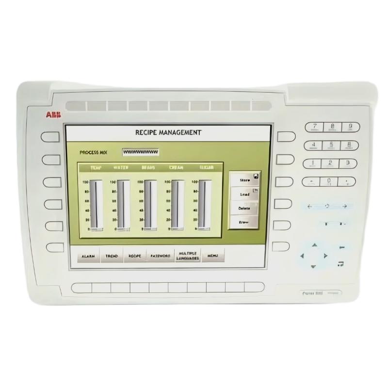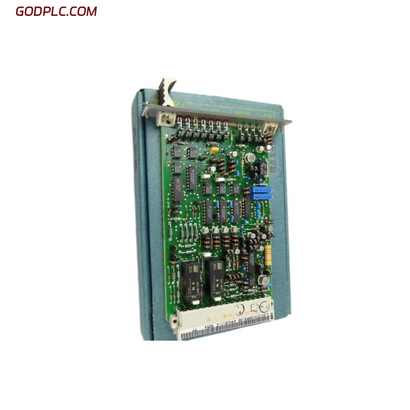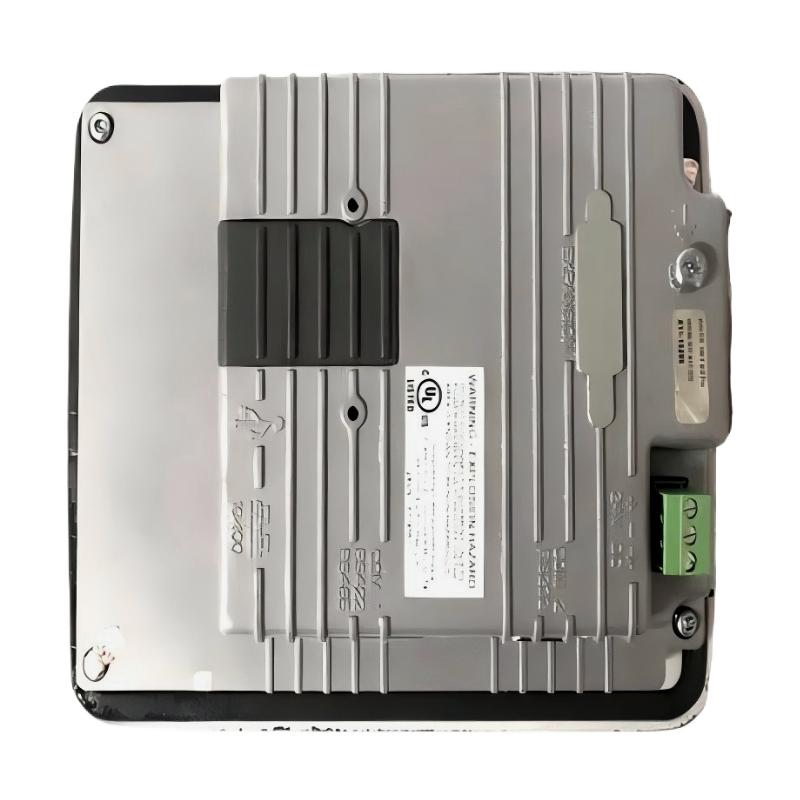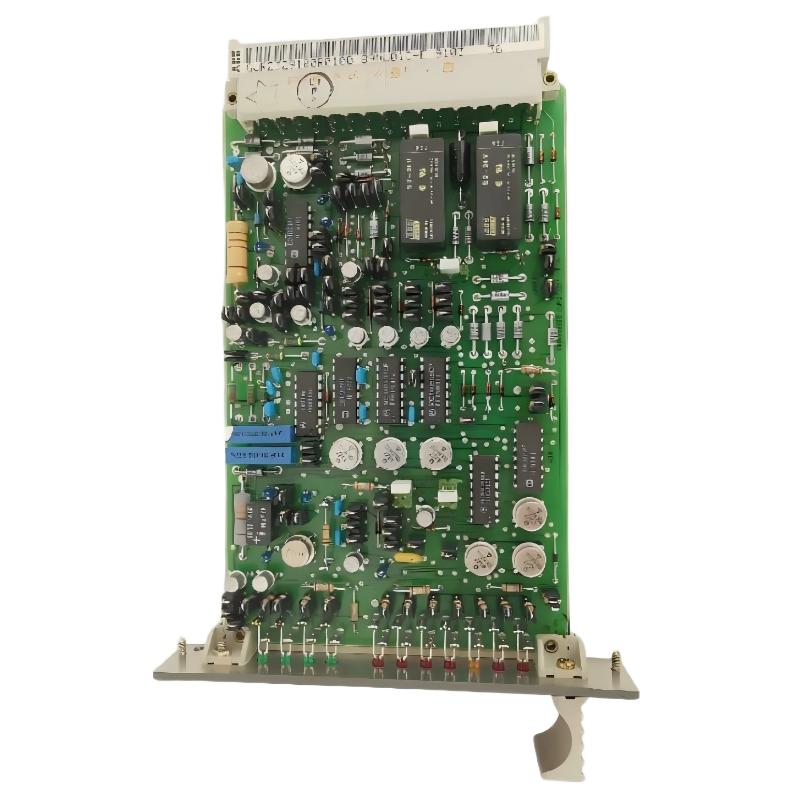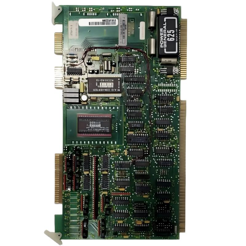
ABB 6100BZ10010B Analog Input Expansion Board Installation Overview
ABB 6100BZ10010B Analog Input Expansion Board installation should begin with system compatibility, power isolation, signal planning, and System Configuration rather than wiring alone. In practical PLC installations, incorrect terminal assignment, unsuitable signal references, and configuration mismatches are more common commissioning problems than a defective expansion board.
ABB 6100BZ10010B Analog Input Module Pre-Installation Checks
Before installing the ABB 6100BZ10010B, verify the host PLC or automation platform, available expansion position, signal type, field transmitter arrangement, and reference potential. The board should be installed only after the associated control system has been isolated according to the site’s electrical safety procedure.
- Confirm the complete 6100BZ10010B part number against the project documentation.
- Check the host rack or controller documentation for supported expansion hardware.
- Identify every analog input channel and its corresponding field instrument.
- Determine whether each field signal is voltage, current, or another supported analog format.
- Inspect connectors, terminals, PCB surfaces, and mounting points for contamination or mechanical damage.
- Separate analog signal cables from high-current motor and contactor wiring where practical.
ABB 6100BZ10010B Analog Input Wiring Strategy
Good analog wiring is mainly about controlling reference potential, noise, and cable routing. Do not assume that connecting a transmitter to an available terminal automatically produces a valid PLC value. The complete signal circuit must be considered from the field device through the input channel and back to the required reference.
For current-loop applications, check the transmitter supply, loop polarity, return path, and measured loop current before relying on the PLC indication. For voltage signals, measure the actual voltage at the expansion board terminals rather than only checking the transmitter output.
- Use correctly identified terminal numbers from the applicable hardware documentation.
- Keep analog pairs together to reduce electromagnetic pickup.
- Use shielded instrumentation cable where the installation environment requires it.
- Apply the site’s approved shield termination and grounding practice consistently.
- Avoid sharing analog returns with noisy power circuits.
ABB 6100BZ10010B PLC System Configuration
After physical installation, the ABB 6100BZ10010B must be represented correctly in the PLC system configuration. The engineering workstation should contain the appropriate hardware definition for the control platform. Channel assignments, scaling parameters, engineering units, and diagnostic handling should match the project design.
A useful commissioning check is to compare three values: the physical signal, the raw input value, and the scaled engineering value. If the physical signal is correct but the PLC value is wrong, investigate configuration and scaling before replacing the board.
CHECK SYSTEM CONFIGURATION
VERIFY MODULE POSITION
VERIFY CHANNEL ASSIGNMENT
VERIFY SIGNAL TYPE
VERIFY INPUT SCALING
VERIFY DIAGNOSTIC STATUS
ABB 6100BZ10010B Setup and Commissioning Validation
The Setup / Commissioning stage should be performed progressively. Energize the control system according to the approved procedure, confirm that the module is recognized, and then validate inputs individually. Applying known field values makes it easier to distinguish wiring errors from scaling errors.
- Confirm that the expansion board is correctly seated and mechanically secured.
- Power the PLC system and inspect available hardware diagnostics.
- Check each configured analog channel for a stable input value.
- Inject or apply a known test signal where the process permits it.
- Compare the measured signal with the PLC raw value.
- Verify the final engineering-unit value in the application program.
- Record abnormal readings before changing configuration parameters.
ABB 6100BZ10010B Field Commissioning Case
In one representative commissioning case involving an analog expansion channel, the field transmitter produced approximately 12.0 mA, while the PLC application displayed a value corresponding to a substantially lower process condition. The first assumption was an input-board fault.
We observed, however, that the measured current was stable at the field device and remained stable at the input terminals. The investigation then moved to System Configuration. The channel had been assigned using the wrong signal range, causing the application scaling to interpret the otherwise valid input incorrectly.
After correcting the channel configuration and application scaling, the PLC indication followed the reference signal correctly. This illustrates an important Installation Guide principle: verify the physical signal before replacing hardware.
ABB 6100BZ10010B Installation FAQ
What should be checked before installing the ABB 6100BZ10010B?
Verify host-system compatibility, module position, field signal type, wiring documentation, connector condition, and the required System Configuration before applying power.
How should analog signals be tested during ABB 6100BZ10010B commissioning?
Measure the actual electrical signal at the input terminals and compare it with the PLC raw value and the final scaled engineering value.
Why can a correct transmitter signal produce an incorrect PLC value?
Incorrect channel assignment, signal-range selection, scaling, reference wiring, or application configuration can cause an incorrect PLC value even when the field transmitter is functioning normally.
Is cable shielding important for ABB 6100BZ10010B analog inputs?
Shielding can be important in electrically noisy environments. The shield should be installed according to the site’s approved grounding practice rather than using an arbitrary termination method.
What is the best way to validate individual analog channels?
Use a known reference signal and verify the complete measurement chain from the field terminal to the PLC diagnostic value and application display.
What should be done if the board is not recognized after installation?
Check seating, connectors, module position, hardware configuration, system diagnostics, and compatible firmware or hardware definitions before concluding that the board itself has failed.
ABB 6100BZ10010B General Installation Summary
The ABB 6100BZ10010B Analog Input Expansion Board Installation Guide should be treated as an engineering verification process rather than a simple wiring task. Correct installation depends on compatible hardware, disciplined signal wiring, accurate System Configuration, and measured validation during Setup / Commissioning. When a channel behaves unexpectedly, comparing the physical signal, raw PLC value, and scaled process value provides a practical starting point for Fault Diagnosis and prevents unnecessary hardware replacement.