
ABB 89IL07A-E Remote Bus Coupling Module Installation Overview
The ABB 89IL07A-E (GJR2394300R0100) Remote Bus Coupling Module is associated with ABB industrial control and Procontrol system applications. A reliable installation depends on confirming the correct hardware revision, control-station compatibility, bus interface, and address configuration before commissioning. If a replacement module is being installed, matching the part number alone is not sufficient; the existing system configuration and the applicable hardware documentation must also be checked.
ABB 89IL07A-E Module Preparation and Compatibility Checks
Before beginning the Installation Guide procedure, establish exactly where the Remote Bus Coupling Module sits in the control architecture. Identify the host controller, station bus, remote bus connections, and any associated interface or processor boards. Record the existing wiring and address settings before removing an installed unit.
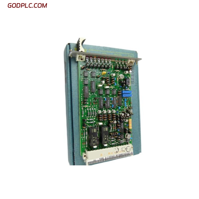
- Verify the complete identification: 89IL07A-E and GJR2394300R0100.
- Compare the replacement hardware revision and board markings with the approved spare-parts specification.
- Obtain the relevant ABB Procontrol system documentation and confirm the permitted mounting position, connector assignments, supply requirements, and addressing method.
- Record current station addresses, communication status, active alarms, and controller configuration.
- Arrange an approved shutdown and isolate the relevant power sources before touching circuit boards or connectors.
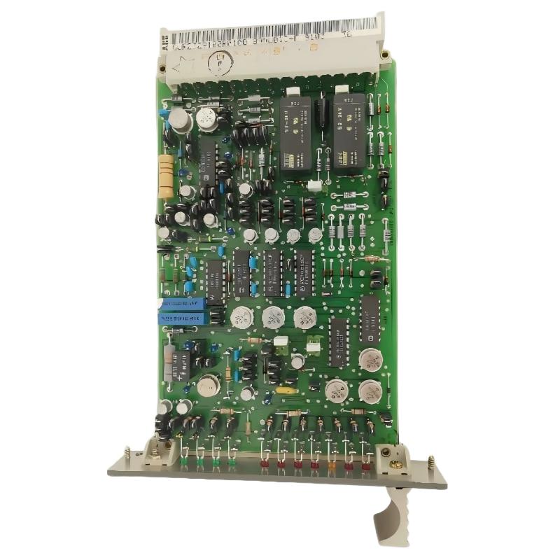
Field experience shows that documenting the original installation is especially valuable on legacy DCS equipment. A photograph of the board and a clear wiring record can prevent address changes or connector swaps from becoming new commissioning faults.
ABB 89IL07A-E Remote Bus Coupling Module Mounting and Wiring
Install the module only in its specified control-station position. Inspect the board, connector pins, retaining hardware, and mating interface for contamination, oxidation, bent contacts, or mechanical damage. Do not force a connector into place or assume that a physically similar board has an identical pin assignment.
- Place the equipment in the approved maintenance state and verify electrical isolation using the site’s safe-work procedure.
- Compare the existing board orientation and connector arrangement against the applicable assembly drawing.
- Inspect the bus cable route for loose terminations, damaged insulation, excessive bending, and potential electromagnetic interference.
- Reconnect the specified interfaces according to the verified wiring diagram. Do not infer terminal numbers, pinouts, or cable polarity from the model name.
- Check that the module is mechanically secure and that no loose screws, tools, or wire fragments remain inside the enclosure.
Grounding, shielding, termination, and cable segregation must follow the specific Procontrol installation requirements. Generic PLC wiring practices should not override the original system design, particularly where a legacy bus uses proprietary electrical interfaces.
ABB 89IL07A-E System Configuration and Commissioning
The commissioning objective is to establish stable communication between the relevant control-station interfaces without introducing an unexpected change to the running control logic. Confirm the station addressing and system configuration against the approved project records before energizing the equipment.
Use the following conceptual checklist to structure the commissioning record. These are documentation prompts, not executable ABB commands.
RECORD module_part_number
RECORD hardware_revision
VERIFY station_address_against_approved_drawing
VERIFY bus_connections_against_wiring_diagram
CHECK controller_and_station_diagnostics
CHECK communication_status
DOCUMENT alarms_before_and_after_startup
The commands above are illustrative pseudocode only. They are not native commands supported by the 89IL07A-E, and they must not be entered into a controller or maintenance terminal as executable instructions.
Restore power only after the inspection is complete and the approved commissioning procedure permits it. Monitor the controller and station diagnostics for communication errors, unexpected station identification, recurring alarms, or inconsistent remote data. Confirm normal operation with the control-room operator before returning the system to service.
ABB 89IL07A-E PLC and DCS Commissioning Validation
A successful power-up does not, by itself, demonstrate that a Remote Bus Coupling Module is functioning correctly. Validation should cover both communication and the process-level consequences of the installation.
- Confirm that the intended station or interface is recognized by the control system.
- Check for active or recurring bus communication alarms.
- Compare diagnostic status and available process data with the recorded baseline.
- Verify that the module address and system configuration match the approved drawings.
- Check that no unrelated controller, station, or process alarms appeared during commissioning.
- Record the installation date, module identifiers, test results, and any configuration changes.
For a controlled acceptance test, use the plant’s approved test procedure and an authorized process window. Never force outputs or interrupt a live control bus simply to demonstrate communication if doing so could compromise process safety.
ABB 89IL07A-E Remote Bus Coupling Module Installation FAQ
Can the ABB 89IL07A-E be replaced without changing the system configuration?
Possibly, but this must be verified. If the replacement has the correct hardware revision and compatible addressing, the original configuration may remain applicable. Confirm the approved spare-parts documentation and compare the actual station settings before startup.
What should be checked before powering up the ABB GJR2394300R0100 module?
Verify the part number, board condition, connector seating, bus wiring, station addressing, and approved supply requirements. Confirm that the control station is in a safe state and that all maintenance work has been cleared.
Does the ABB 89IL07A-E use a standard Ethernet or RS-485 connection?
Do not assume that it uses either interface. The exact physical bus, pin assignment, and electrical characteristics must be established from the documentation for the specific Procontrol hardware and installation.
ABB 89IL07A-E Installation Conclusion and General Notes
The ABB 89IL07A-E GJR2394300R0100 Remote Bus Coupling Module should be installed through a controlled process covering identification, mechanical inspection, verified wiring, system configuration, and functional commissioning. Because this is a legacy industrial control component, model-specific connection details and address-setting procedures must be confirmed against the correct ABB documentation rather than guessed. A recorded baseline and a documented post-installation communication check provide the clearest evidence that the replacement is ready for service.