100% Original, Ready to Ship!

ABB DI 685 3BSE011613R1 Numeric Input Module Installation Guide
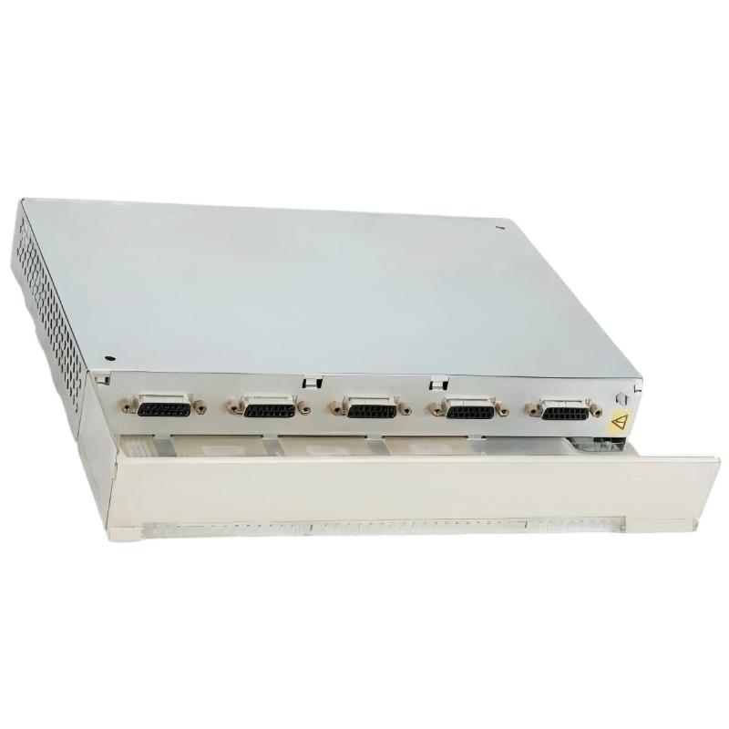
ABB DI685 3BSE011613R1 Digital Input Module Installation Overview
The ABB DI685 3BSE011613R1 digital input module is designed for discrete signal acquisition in ABB S600 I/O and compatible Advant control system configurations. Successful installation depends on correct rack compatibility, field wiring, input voltage selection, and System Configuration. Although the supplied product description identifies this item as a Numeric Input Module, available product information identifies DI685 as a digital input unit. Confirm the exact hardware designation and revision before commissioning.
This Installation Guide focuses on practical preparation, electrical verification, and commissioning checks for industrial control cabinets. The exact terminal assignments, permissible input voltages, and diagnostic functions must be verified against the applicable ABB hardware documentation.
ABB DI685 Module Installation Guide Contents
- Module Role and System Compatibility
- Installation Preparation and Safety
- DI685 Field Wiring and Signal Checks
- System Configuration and Commissioning
- Field Commissioning Investigation
- Installation FAQ
- General Conclusion
ABB DI685 3BSE011613R1 Module Role and Compatibility
The DI685 receives discrete field states and makes them available to the control system. Typical applications include auxiliary contacts, limit switches, machine status contacts, and other binary process signals, provided that the field-device electrical characteristics match the module specification.
- Manufacturer: ABB.
- Model: DI685.
- Part number: 3BSE011613R1.
- Product type: Digital input module.
- Reported platform: ABB S600 I/O and compatible Advant control configurations.
- Reported input categories: 24 V DC and 48 V DC applications; verify the exact supported signal range for the installed hardware.
Do not select a replacement based on the DI685 model name alone. Compare the complete part number, hardware revision, terminal unit, rack compatibility, and existing project configuration before installation.
ABB DI685 Installation Preparation and Electrical Safety
Before opening the control cabinet, review the approved electrical drawings and the site’s isolation procedure. A digital input circuit can remain energized even when the controller rack is switched off because field devices may have a separate 24 V DC or 48 V DC supply.
- Record the existing module identification and terminal wiring before disconnection.
- Confirm the rack position and the compatibility of the module with the installed I/O system.
- Verify the field supply voltage and the electrical output type of each connected device.
- Inspect the connector, terminal block, backplane interface, and cabinet grounding.
- Apply the approved lockout/tagout procedure and verify the absence of hazardous voltage before handling conductors or removing hardware.
- Use suitable ESD protection when handling the electronic module.
Field experience shows that a module replacement can be delayed by incorrect terminal identification rather than a defective component. Photographing the original wiring and comparing it with the electrical drawing helps prevent cross-connected signals during reinstallation.
ABB DI685 Digital Input Wiring and Signal Verification
Correct wiring requires more than matching wire numbers. The technician must establish the signal reference, the field supply polarity, the common-terminal arrangement, and the expected electrical state of every input.
- Use the terminal diagram for the exact DI685 hardware and terminal assembly.
- Check whether each field device provides a dry contact or an electrically powered signal.
- Confirm that the field voltage is within the documented input range.
- Inspect for loose terminals, damaged insulation, short circuits, and incorrect common connections.
- Route low-level input wiring away from high-current switching conductors where practical.
- Apply cable shielding and grounding according to the project design and ABB installation instructions.
Never assume that all DI685 terminals share the same reference or that a generic digital input pinout applies to this unit. Incorrect polarity or an incompatible voltage can cause unreliable status indication or damage connected equipment.
ABB DI685 Input Voltage Measurement
Use a calibrated multimeter and the approved test procedure to measure the field signal at the designated terminals. The following values are examples of a measurement record, not guaranteed DI685 switching thresholds.
| Test item | Expected observation | Engineering action |
|---|---|---|
| Field supply | Within the documented supply range | Correct the supply if out of specification. |
| Contact open | Input matches the designed inactive state | Check leakage, wiring, and input logic. |
| Contact closed | Input reaches the documented active state | Check the contact path and voltage drop. |
| Common reference | Correct connection according to the terminal diagram | Repair incorrect or missing references. |
ABB DI685 System Configuration and Commissioning
After the physical installation, verify that the controller project recognizes the correct I/O hardware and that the process variables correspond to the intended physical channels. A module can be correctly seated and electrically healthy while the application still reads the wrong signal because of an addressing or configuration mismatch.
- Confirm that the installed module matches the configured hardware entry.
- Check rack position, channel mapping, and any required I/O configuration parameters.
- Review the controller’s hardware diagnostics for missing-module or communication indications.
- Operate one field device at a time and compare its physical state with the corresponding controller input.
- Test all required channels and record the results before releasing the system to production.
- Verify interlocks and permissives using the approved commissioning procedure.
ABB DI685 Commissioning Diagnostic Commands
The following pseudocode illustrates the checks an engineer can document during commissioning. It is not executable ABB software syntax and does not represent a native DI685 command set.
CHECK module_identity
CHECK rack_slot_against_project
CHECK controller_hardware_diagnostics
FOR each_required_input:
    VERIFY field_device_state
    MEASURE field_signal_at_designated_terminals
    COMPARE physical_state_with_controller_status
    RECORD pass_or_fail
END
Do not force production inputs or bypass protective interlocks merely to complete an I/O test. Any simulation or forcing must follow the site’s authorization, risk assessment, and restoration procedures.
ABB DI685 Field Commissioning Investigation
Illustrative commissioning scenario: A limit switch changes state in the field, but the controller input remains inactive. The technician first checks the switch itself, then measures the signal at the approved terminal points, and finally compares the physical channel with the project mapping.
Suppose the field circuit is designed for 24 V DC and the technician measures 24.1 V DC at the supply terminals. This reading supports the conclusion that the supply is present at that measurement point; it does not prove that the input terminal receives the correct signal under load. The next checks are the contact output, return path, terminal connections, and actual input status.
If the signal reaches the correct module terminal but the controller still reports the wrong state, the investigation should move to channel assignment, hardware configuration, and module diagnostics. If the voltage is absent at the module, the technician should investigate the field circuit before replacing the module.
This is a representative diagnostic example, not a claim about a verified customer incident. Actual readings, switching thresholds, and acceptance criteria must come from the installed equipment documentation and site measurements.
ABB DI685 Installation and Commissioning FAQ
What is the function of the ABB DI685 3BSE011613R1 module?
DI685 is identified as a digital input unit used to acquire discrete field signals in compatible ABB control-system configurations. It should not be confused with an analog numeric input module without confirming the exact product identity.
Which voltage should be used for ABB DI685 input wiring?
Product listings report 24 V DC and 48 V DC applications for DI685 variants. Confirm the permitted input range, signal type, and terminal arrangement in the documentation for the exact installed unit before energizing the circuit.
How can ABB DI685 commissioning errors be reduced?
Verify the part number, rack position, terminal connections, field supply, channel mapping, and controller diagnostics. Test each required input individually and record the physical state alongside the controller indication.
Can the ABB DI685 be removed while the control system is running?
Do not assume hot-swap capability. Follow the exact hardware manual and the site’s approved isolation procedure before removing or inserting the module.
What should be checked if an ABB DI685 input does not change state?
Check the field device, supply voltage, return path, terminal connections, input compatibility, configured channel, and controller diagnostics in that order. Replace the module only after external wiring and configuration have been assessed.
Does the ABB DI685 require System Configuration?
System Configuration must be checked to ensure that the controller recognizes the hardware and assigns the correct input channels. The exact configuration procedure depends on the installed ABB control platform and engineering software.
ABB DI685 Installation Guide: General Conclusion
Reliable ABB DI685 3BSE011613R1 installation depends on hardware compatibility, correct field wiring, verified electrical conditions, and systematic commissioning. The most useful acceptance record includes the module identity, terminal checks, field measurements, channel-by-channel test results, and controller diagnostic status. Use the exact ABB documentation for terminal assignments and electrical limits, and do not place the system into service until all required checks have passed.
 ABB SS110 3BSE007698R1 Voting Unit Installation Guide
 ABB DX522 1SAP245200R0001 Digital Input/Output Module Installation Guide
 ABB SD823 3BSC610039R1 Power Supply Installation Guide
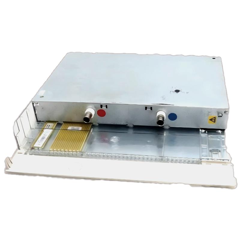 ABB DI685 3BDS005833R1 Digital Input Module Installation Guide