100% Original, Ready to Ship!

ABB SS110 3BSE007698R1 Voting Unit Installation Guide
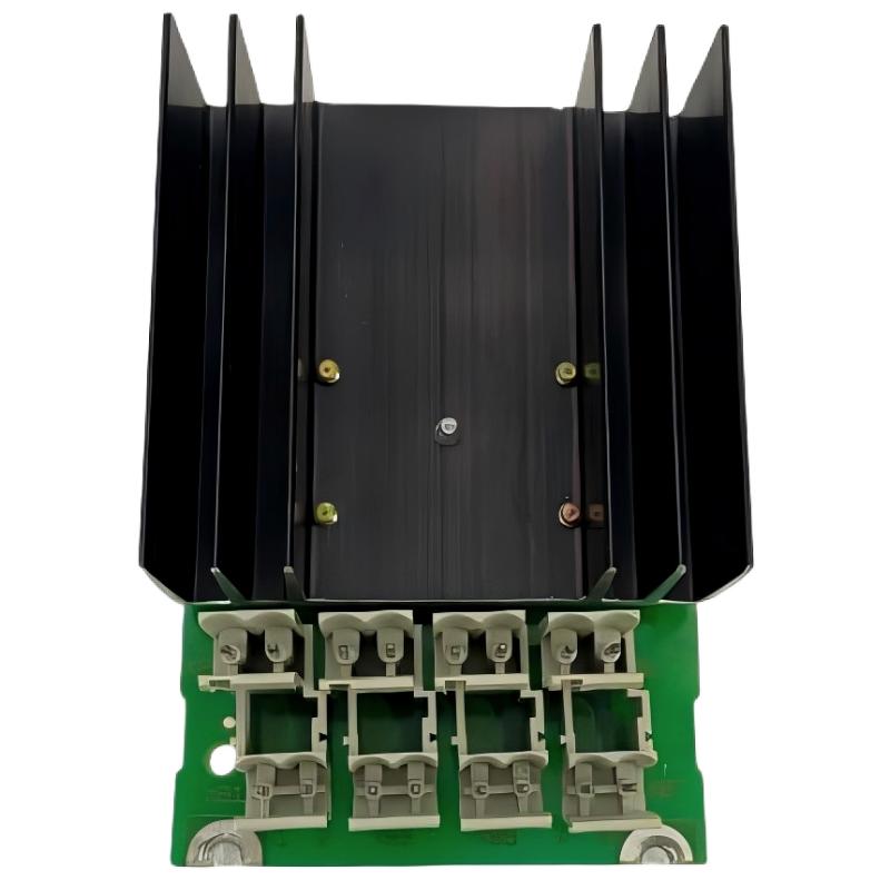
ABB SS110 3BSE007698R1 Voting Unit Installation Overview
The ABB SS110 3BSE007698R1 is a 24V DC voting unit designed to combine two redundant DC power supply lines into a single output path. In ABB Advant control system architectures, the SS110 helps maintain power continuity when one of the two incoming supply sources becomes unavailable. Correct installation of this ABB Voting Unit is essential for reliable redundant power distribution, especially in industrial control environments where unexpected power interruptions can affect the entire process.
This Installation Guide covers hardware preparation, power connections, System Configuration, commissioning checks, and practical engineering considerations for the ABB SS110 power voting unit.
Understanding the ABB SS110 24V DC Power Voting Function
Unlike a conventional standalone Power Supply Module, the ABB SS110 performs a voting function on two DC power input lines. Its purpose is to support a redundant power arrangement by allowing the system to maintain its output when one supply branch experiences a fault, subject to the specified operating conditions and correct system design.
The main identification details are:
- Manufacturer: ABB
- Model: SS110
- Product Number: 3BSE007698R1
- Product Description: Voting Unit DC 24V
- Product Category: Power Distribution and Voting Unit
- Typical Application: Redundant 24V DC power distribution
- System Environment: ABB Advant industrial control systems
Before installation, engineers should distinguish the SS110 from ordinary 24V DC power supplies. It is a voting device, not a replacement for the upstream power supply units.
Installation Preparation for ABB SS110 3BSE007698R1
Proper preparation reduces commissioning errors and prevents damage to the redundant power architecture. Before mounting the ABB SS110, inspect the device and confirm that its product identification matches the equipment list and approved electrical drawings.
Hardware and Documentation Inspection
- Check the SS110 product number and hardware condition.
- Inspect terminals and connectors for oxidation, deformation, or loose components.
- Confirm that both DC supply branches are available.
- Review the original ABB installation documentation and system wiring diagrams.
- Verify enclosure temperature, ventilation, and installation space.
- Prepare suitable electrical test equipment.
Electrical Safety Before Mounting
Disconnect and isolate both incoming power sources before performing electrical installation. A redundant power arrangement may remain energized through the second supply branch even when the first branch has been disconnected.
Apply the site’s lockout/tagout procedure and verify the absence of hazardous voltage before touching conductors or terminals.
ABB SS110 Voting Unit Wiring and Connection Strategy
The electrical installation should follow the approved ABB system diagram. The two incoming 24V DC supply branches must remain electrically independent up to their designated SS110 input connections. The voted output is then connected to the intended downstream load distribution circuit.
Typical Redundant Power Architecture
DC Power Supply A (+24V)
          |
          |
     SS110 Input A
          |
          |
     ABB SS110
     Voting Unit
          |
          |
     SS110 Output
          |
          |
   Downstream DC Load


DC Power Supply B (+24V)
          |
          |
     SS110 Input B
This is a functional architecture illustration, not a terminal-level wiring diagram. Actual terminal assignments, polarity, conductor sizes, grounding arrangements, and permissible load conditions must be verified against the applicable ABB documentation.
Important Wiring Considerations
- Input separation: Keep supply A and supply B identifiable throughout the installation.
- Polarity: Verify positive and negative connections before energizing the unit.
- Protection: Confirm that upstream branch protection is appropriate for the connected equipment.
- Load compatibility: Check the downstream load requirements against the SS110 ratings.
- Terminal security: Tighten connections according to the manufacturer’s specified torque.
- Cable routing: Avoid unnecessary proximity to high-current switching cables and sources of electrical interference.
ABB SS110 System Configuration and Commissioning Checks
After completing the physical installation, commissioning should focus on the behavior of both incoming power branches and the common output. A successful initial voltage measurement does not automatically prove that the redundancy function is operating correctly.
Initial Power Verification
- Confirm that both upstream 24V DC supplies are within their approved operating ranges.
- Check the input polarity and terminal connections.
- Measure the voltage at the designated SS110 input points using an appropriate meter.
- Energize the system according to the approved commissioning procedure.
- Measure the voted output under normal operating conditions.
- Compare the readings with the equipment documentation and downstream load requirements.
Redundancy Functional Test
Where permitted by the process safety plan, perform a controlled supply-loss test. Simulate the loss of one incoming supply branch while keeping the other branch available. Observe the common output and downstream equipment response.
CHECK INPUT_A_VOLTAGE
CHECK INPUT_B_VOLTAGE
CHECK COMMON_OUTPUT_VOLTAGE

IF SUPPLY_A_IS_ISOLATED:
    VERIFY_OUTPUT_REMAINS_WITHIN_LIMITS

RESTORE SUPPLY_A
VERIFY_NORMAL_OPERATION

IF SUPPLY_B_IS_ISOLATED:
    VERIFY_OUTPUT_REMAINS_WITHIN_LIMITS

RESTORE SUPPLY_B
RECORD_FINAL_MEASUREMENTS
The commands above represent a commissioning checklist in pseudocode, not executable ABB controller instructions.
Practical ABB SS110 Commissioning Experience
Consider an illustrative commissioning scenario involving an ABB Advant control cabinet with two independent 24V DC power supply branches. During the initial inspection, the engineering team finds that both supplies operate normally, but the common output voltage changes when one branch is disconnected.
Rather than immediately replacing the SS110, the engineer checks the input voltage at both branches, reviews the wiring diagram, and measures the common output under a stable downstream load.
The investigation focuses on three possible areas:
- Incorrect input wiring or polarity.
- A voltage drop caused by loose terminals or undersized conductors.
- An abnormal condition inside the voting unit.
After correcting the identified connection issue, the engineer repeats the controlled redundancy test and records the input and output measurements. This type of fault-isolation approach is more reliable than replacing hardware based only on a single voltage reading.
This is an illustrative engineering scenario, not a documented ABB field-service report. Actual acceptance values must come from the applicable equipment specifications.
ABB SS110 Installation Mistakes to Avoid
- Connecting both supply branches without confirming their electrical independence.
- Assuming that the SS110 generates 24V DC like a conventional power supply.
- Using an unverified terminal arrangement based on another ABB voting unit.
- Ignoring voltage drop between the voting unit and downstream equipment.
- Performing redundancy tests without an approved maintenance or bypass procedure.
- Installing a replacement without checking its complete product identification.
ABB SS110 Installation and Commissioning FAQ
What is the main function of the ABB SS110 3BSE007698R1?
The ABB SS110 is a 24V DC voting unit designed for redundant power distribution. It combines two DC supply inputs into a common output path to support power continuity when one input supply becomes unavailable.
Is ABB SS110 a conventional 24V DC power supply?
No. The SS110 is a voting unit rather than a standalone power generator. It works with external DC power supplies in a redundant power architecture.
Can the ABB SS110 operate with only one power supply?
Its voting function is intended to support a redundant arrangement with two incoming supply branches. Whether single-input operation is acceptable depends on the system design, electrical ratings, and application requirements.
What should be checked before ABB SS110 commissioning?
Check the product identification, input polarity, both supply voltages, terminal security, output voltage, and downstream load compatibility. The final verification should include a controlled redundancy test.
Does the ABB SS110 require controller software configuration?
The SS110 is primarily a hardware power voting device. Its installation and functional verification depend on the electrical System Configuration. Any related system alarms or monitoring functions should be checked against the installed ABB control system documentation.
Conclusion: ABB SS110 Power Voting Unit Installation
Successful installation of the ABB SS110 3BSE007698R1 requires more than simply connecting two 24V DC supplies. Engineers must preserve the intended redundancy architecture, verify electrical compatibility, inspect terminal connections, and perform controlled commissioning tests. A systematic Installation Guide and documented Setup procedure help reduce wiring mistakes and improve the reliability of ABB Advant power distribution systems. Always use the applicable ABB technical documentation for final terminal assignments and operating limits.
 ABB DX522 1SAP245200R0001 Digital Input/Output Module Installation Guide
 ABB SD823 3BSC610039R1 Power Supply Installation Guide
 ABB DI685 3BDS005833R1 Digital Input Module Installation Guide
 ABB SD821 3BSC610037R1 Power Supply Installation Guide