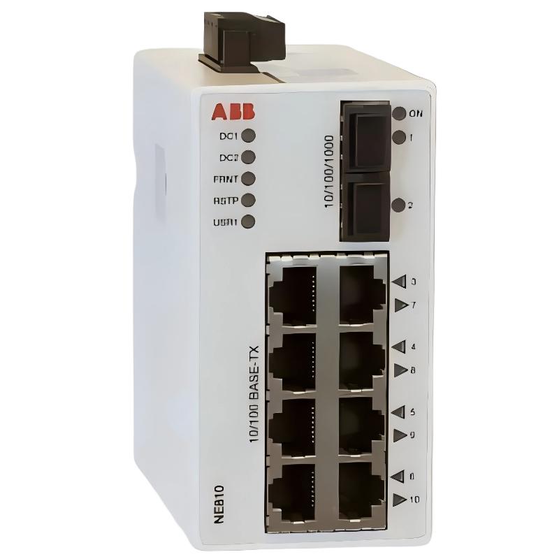
ABB NE810 3BSE080207R1 Industrial Ethernet Switch Installation Guide
The ABB NE810 3BSE080207R1 Industrial Ethernet Switch is a managed Layer 2 network switch designed for industrial communication systems, including ABB System 800xA installations. Correct installation requires attention to redundant 19–60 VDC power connections, Ethernet port allocation, SFP transceiver compatibility, and FRNT network redundancy configuration. During Setup and Commissioning, verifying the physical network topology before connecting operational controllers is essential for preventing unexpected communication interruptions.
Contents of the ABB NE810 Switch Installation Guide
- Industrial Network Application
- Installation Preparation and Technical Checks
- DIN Rail Mounting and Power Wiring
- Ethernet and SFP Network Configuration
- System Configuration and Commissioning
- Network Validation and Field Inspection
- Installation FAQ
- Installation Summary
ABB NE810 Industrial Ethernet Switch Role in Automation Networks
The NE810 is a 10-port managed industrial Ethernet switch intended for communication infrastructure rather than direct process I/O control. It provides eight 10/100 Mbit/s Ethernet ports and two SFP interfaces supporting 10/100/1000 Mbit/s connections.
In an ABB System 800xA environment, the switch can provide network connectivity between controllers, operator stations, engineering workstations, and other compatible Ethernet devices.
Its main technical characteristics include:
- Eight RJ45 Ethernet ports operating at 10/100 Mbit/s.
- Two SFP ports supporting 10/100/1000 Mbit/s.
- Managed Layer 2 switching functionality.
- FRNT network redundancy support.
- Redundant DC power input.
- DIN rail mounting.
- IP40 enclosure protection.
One important engineering distinction is that the NE810 is not an Ethernet firewall. Network segmentation and cybersecurity protection must therefore be addressed through the wider automation network architecture.
ABB NE810 Installation Preparation and Technical Checks
Before installing the ABB NE810 3BSE080207R1, verify the equipment identification and confirm that the selected network architecture is compatible with the existing control system.
The following preparation checks are recommended:
- Confirm that the equipment label identifies NE810 and article number 3BSE080207R1.
- Inspect the enclosure for mechanical damage and contamination.
- Check that the control cabinet provides sufficient DIN rail space.
- Verify the DC supply voltage is within 19–60 VDC.
- Confirm that both power supply paths are correctly designed if redundant power is required.
- Identify the required copper Ethernet cables and SFP transceivers.
- Check fiber type, wavelength, connector type, and optical link budget.
- Review the existing network topology and redundancy design.
The NE810 has a rated current of 240 mA at 24 VDC and 120 mA at 48 VDC. Power supply capacity should be assessed using the actual cabinet load and applicable engineering margins rather than relying only on nominal current consumption.
ABB NE810 Environmental and Mechanical Requirements
The published operating temperature range is -40°C to +70°C, while the storage temperature range is -50°C to +85°C. The enclosure protection rating is IP40.
Its published dimensions are 52 × 100 × 101 mm, with a weight of approximately 0.7 kg. Allow additional cabinet space for cable routing, connector access, and maintenance clearance.
ABB NE810 DIN Rail Mounting and Power Wiring
The NE810 is designed for DIN rail installation. Select a mounting position that provides mechanical stability and allows technicians to inspect the front panel and access communication connections without disturbing neighboring equipment.
For power installation, observe the following engineering practices:
- Isolate the cabinet power source and apply the site’s electrical safety procedures.
- Inspect the DC supply wiring and verify polarity before connecting the device.
- Connect the first DC supply according to the manufacturer’s terminal identification.
- Connect the independent redundant supply path when the system design requires power redundancy.
- Check terminal tightness and ensure that conductors are properly secured.
- Verify the DC voltage at the equipment terminals before energizing the switch.
The NE810 supports a redundant 19–60 VDC power input. Redundant power is useful in control cabinets where maintaining network availability during a power supply failure is important. However, connecting two power feeds does not automatically provide complete power redundancy if both feeds originate from the same unprotected source.
ABB NE810 Power Installation Inspection
For a nominal 24 VDC installation, verify that the measured supply voltage remains within the permitted operating range under normal load conditions. Check for loose terminals, excessive voltage drop, and unstable power during switching operations.
Do not assume that a power indicator alone confirms correct operation of the complete industrial Ethernet network. Power status and communication status must be checked separately.
ABB NE810 Ethernet and SFP Network Configuration
Network cabling should follow the approved System Configuration drawing. The eight RJ45 ports are suitable for compatible 10/100 Mbit/s Ethernet devices, while the two SFP interfaces provide higher-speed optical or compatible copper connectivity through approved transceivers.
Before connecting an SFP module, verify the following:
- Supported transceiver model and interface compatibility.
- Multimode or single-mode fiber selection.
- Optical wavelength compatibility at both ends.
- Transmission distance and optical power budget.
- Correct fiber polarity and connector cleanliness.
ABB lists compatible SFP product options for the NE810, including multimode, single-mode, BiDi, and RJ45 variants. The selected transceiver must match the remote interface rather than simply fitting the physical connector.
Network Topology and FRNT Configuration
The NE810 supports FRNT, which provides fast network topology reconfiguration following certain network failures. When designing a redundant network, engineers must ensure that the topology, switch configuration, and connected equipment are compatible with the intended redundancy scheme.
Do not create uncontrolled Ethernet loops during initial installation. Confirm the approved FRNT configuration and avoid combining incompatible redundancy mechanisms without a documented network design.
ABB NE810 System Configuration and Commissioning Procedure
Commissioning should begin with the isolated switch and gradually progress toward the complete automation network. This makes it easier to distinguish hardware installation problems from network configuration errors.
A practical commissioning sequence includes:
- Power up the NE810 without connecting the complete production network.
- Check the power indicators and inspect the physical condition of all interfaces.
- Establish the required management connection using the approved ABB documentation.
- Verify the switch management configuration and network identification.
- Check the Ethernet port assignments against the network drawing.
- Configure and verify FRNT where required by the approved architecture.
- Connect the designated controllers and supervisory system devices.
- Monitor communication stability before releasing the network for operation.
The actual management interface, firmware behavior, and available configuration options should be verified against the installed NE810 hardware and applicable documentation. Do not apply configuration commands intended for unrelated switch models.
ABB NE810 Commissioning Diagnostic Reference
The following is a generic diagnostic checklist, not a manufacturer-specific command set:
DEVICE: ABB NE810
ARTICLE: 3BSE080207R1

CHECK POWER:
  DC_INPUT_1 = VERIFY
  DC_INPUT_2 = VERIFY
  VOLTAGE_RANGE = 19-60 VDC

CHECK INTERFACES:
  RJ45_PORTS = 8
  SFP_PORTS = 2

CHECK NETWORK:
  LINK_STATUS = VERIFY
  PORT_ASSIGNMENT = VERIFY
  FIBER_COMPATIBILITY = VERIFY
  FRNT_STATUS = VERIFY

CHECK SYSTEM:
  CONTROLLER_COMMUNICATION = VERIFY
  NETWORK_REDUNDANCY = TEST
ABB NE810 Network Validation and Field Inspection
During commissioning, a common engineering mistake is to investigate controller communication problems before checking the physical Ethernet layer. In practice, an incorrectly matched SFP transceiver, damaged fiber connector, or incorrectly assigned network port can produce symptoms that appear to originate from the PLC Controller.
Consider an illustrative commissioning scenario in which a remote controller cannot establish stable communication through an optical connection. The engineering investigation should compare the local and remote SFP specifications, inspect the fiber connectors, and verify the physical link before changing controller communication settings.
For example, if a measured DC input is 23.8 VDC, that value is within the specified 19–60 VDC operating range. It does not, however, prove that the optical connection or network redundancy configuration is correct.
Final acceptance should include:
- Stable power supply operation.
- Correct port-to-device mapping.
- Consistent Ethernet link status.
- Correct optical interface matching.
- Successful communication with connected automation equipment.
- Successful verification of the designed network redundancy behavior.
- Updated cabinet drawings and network configuration records.
ABB NE810 3BSE080207R1 Installation FAQ
Can the ABB NE810 operate with a 24 VDC power supply?
Yes. The NE810 supports 19–60 VDC input and has a rated current of 240 mA at 24 VDC. Verify the available power supply capacity and terminal wiring before commissioning.
How many Ethernet connections does the ABB NE810 provide?
The NE810 provides eight 10/100 Mbit/s RJ45 Ethernet ports and two SFP ports supporting 10/100/1000 Mbit/s connections.
Does the ABB NE810 support redundant power?
Yes. It supports redundant DC power input. For effective redundancy, the two supply paths should be designed to minimize common power failure risks.
What is the function of FRNT in the ABB NE810?
FRNT is used for network redundancy and fast reconfiguration of the network topology following certain communication path failures.
Can the NE810 be installed on a DIN rail?
Yes. The NE810 is designed for DIN rail mounting and is suitable for industrial control cabinet installations.
Is the ABB NE810 a Layer 2 or Layer 3 switch?
The NE810 is a managed Layer 2 industrial Ethernet switch. It should not be treated as a Layer 3 router or firewall.
What should be checked before connecting an SFP transceiver?
Verify the transceiver compatibility, fiber mode, wavelength, connector type, transmission distance, and optical power budget at both ends of the communication link.
What is the operating temperature range of the ABB NE810?
The specified operating temperature range is -40°C to +70°C. The storage temperature range is -50°C to +85°C.
ABB NE810 Installation and Commissioning Summary
Successful installation of the ABB NE810 3BSE080207R1 depends on correct power wiring, compatible Ethernet interfaces, properly selected SFP transceivers, and a carefully verified network redundancy design. A structured Installation Guide and Setup / Commissioning process helps reduce communication interruptions and simplifies future maintenance. Before placing the industrial switch into service, engineers should verify all physical connections, network parameters, and communication paths against the approved automation system documentation.