100% Original, Ready to Ship!

ABB SS822 3BSC610042R1 Power Voting Unit Installation Guide

ABB SS822 3BSC610042R1 Power Voting Unit Installation Overview
The ABB SS822 3BSC610042R1 Power Voting Unit is designed to maintain a reliable 24 V DC power supply in industrial automation systems using redundant power sources. It accepts two independent 24 V DC inputs, each rated at up to 20 A, and provides a single 24 V DC output with a maximum rated output current of 20 A. During installation, the most important considerations are input polarity, power-source compatibility, terminal integrity, and correct supervision wiring.
Unlike a conventional standalone power supply, the ABB SS822 operates as a power voting and supervision device. It is commonly integrated with ABB SD821, SD822, and SD823 power supply units in redundant power configurations. This Installation Guide explains the practical mounting, electrical connection, Setup, and Commissioning procedures for the SS822 Power Voting Unit.
ABB SS822 Power Voting Unit Function in Redundant Systems
The SS822 is installed downstream of two compatible power supply units. Its internal power management arrangement allows the control system to continue receiving power when one input supply becomes unavailable, provided the remaining source can support the connected load.
- Power input A: Independent 24 V DC supply.
- Power input B: Second independent 24 V DC supply.
- Power output: Single 24 V DC distribution connection.
- Rated output current: 20 A.
- Input supervision: Individual monitoring of both power inputs.
- Mounting: DIN rail installation.
- Compatible power supplies: ABB SD821, SD822, and SD823.
For system designers, the main advantage is improved power availability without requiring separate manual switching arrangements. However, redundancy is only effective when both upstream power supplies have independent and appropriately protected power paths.
ABB SS822 Installation Preparation and System Configuration
Before installing the ABB 3BSC610042R1 module, inspect the existing control cabinet and confirm that the available power sources match the intended redundant power architecture.
Required Installation Checks
- Confirm the complete product identification: SS822, 3BSC610042R1.
- Check the condition of the enclosure, terminal connections, and mounting interface.
- Verify that both upstream supplies provide regulated 24 V DC power.
- Confirm that the expected load does not exceed the 20 A rated output current.
- Check that the cabinet provides sufficient ventilation.
- Review the ABB hardware documentation for the correct terminal arrangement.
- Prepare suitable DC-rated circuit protection for each supply branch.
The SS822 has a nominal installation width of 50 mm and mounting dimensions of approximately 125 × 110 mm (height × depth). Its protection rating is IP20, so it should be installed inside an appropriately protected electrical cabinet.
Electrical Conditions to Verify
| Parameter | Specification |
|---|---|
| Product Model | ABB SS822 |
| Part Number | 3BSC610042R1 |
| Input Configuration | Dual 24 V DC |
| Rated Output Voltage | 24 V DC |
| Rated Output Current | 20 A |
| Maximum Input Voltage | 35 V DC |
| Rated Input Power | 500 W |
| Maximum Ambient Temperature | 55°C |
| Heat Dissipation | 10 W at 20 A |
| Mounting | DIN Rail |
| Protection Rating | IP20 |
ABB SS822 Power Supply Wiring and Connection Procedure
Correct wiring is essential for reliable redundant power operation. Both DC power sources must be checked independently before they are connected to the SS822.
Dual Power Input Arrangement
Connect the first compatible power supply to the designated input A terminals and the second supply to the designated input B terminals. Follow the terminal markings and connection diagram for the exact 3BSC610042R1 hardware revision.
- Disconnect and isolate both upstream power supplies.
- Verify that the DC output polarity of each supply is correct.
- Connect the first 24 V DC source to input A.
- Connect the independent 24 V DC source to input B.
- Connect the common output terminals to the intended control-system power distribution circuit.
- Connect the supervision contacts to the appropriate monitoring circuit if required by the system design.
- Inspect all conductors for loose strands, damaged insulation, and incorrect terminal placement.
Do not assume that terminal positions are identical across different ABB power devices. Use the SS822 connection diagram rather than relying on wire colors or the layout of another module.
ABB SS822 Terminal and Wiring Considerations
- Input and output solid conductor size: 0.5–6 mm².
- Input and output stranded conductor size: 0.5–4 mm².
- Recommended input/output terminal tightening torque: 0.8 Nm.
- Supervision terminal conductor size: 0.2–1.5 mm².
- Recommended supervision terminal tightening torque: 0.8 Nm.
Actual conductor selection must account for installation temperature, cable length, voltage drop, protective devices, and applicable electrical regulations. The maximum current rating of the SS822 does not automatically establish the permissible current for every connected cable.
ABB SS822 DIN Rail Mounting and Mechanical Setup
The ABB SS822 Power Voting Unit is designed for DIN rail mounting. Before securing the unit, inspect the rail for deformation and ensure that sufficient cabinet space is available for wiring access and heat dissipation.
- Install the unit on the specified DIN rail.
- Confirm that the mounting latch is fully engaged.
- Maintain sufficient clearance for terminal access.
- Route DC power cables separately from high-noise switching conductors where practical.
- Prevent cable tension from transferring directly to the terminals.
- Ensure that the enclosure environment remains within the specified operating conditions.
Because the SS822 can dissipate approximately 10 W at a 20 A load, cabinet temperature and airflow should be considered during System Configuration.
ABB SS822 Setup and Commissioning Verification
Commissioning should begin with the two input supplies tested separately. This makes it easier to identify incorrect polarity, unstable DC voltage, or an input branch that cannot support the intended load.
Input Supply Verification
Measure the voltage at input A and input B before evaluating the combined output. Both readings should be consistent with the intended 24 V DC system configuration.
The SS822 supervision thresholds provide additional diagnostic reference points:
- Low-voltage trip level during decreasing voltage: 22 V.
- Low-voltage hysteresis: 0.7 V.
- High-voltage trip level during rising voltage: 30 V.
- High-voltage hysteresis: 0.7 V.
These thresholds are factory preset. They should not be treated as adjustable operating setpoints.
Output and Supervision Checks
- Restore the first power supply and inspect its corresponding front-panel indication.
- Restore the second power supply and verify its individual indication.
- Measure the combined output voltage under an appropriate load.
- Check that the output remains stable when the load changes.
- Verify the supervision contacts against the actual system wiring.
- Perform an approved single-source failure test.
- Restore both supplies and confirm that normal redundant operation returns.
The output voltage can be approximately 0.5 V below the input voltage at maximum rated current. This should be considered when checking downstream equipment voltage requirements.
ABB SS822 Power Voting Unit Commissioning Example
Illustrative engineering example: Consider an ABB control cabinet equipped with two SD822 power supplies and an SS822 Power Voting Unit. During initial commissioning, the technician measures 24.2 V DC at input A and 24.1 V DC at input B.
The combined output is then checked under a controlled load. If the output voltage is lower than expected, the technician should compare the voltage directly at the SS822 input terminals with the voltage at the output terminals. This separates upstream supply problems from connection resistance and downstream load problems.
For example, a measured output of 23.6 V DC at a suitable test load should be evaluated against the actual input voltage, current, and expected voltage drop. It should not automatically be classified as an SS822 hardware failure.
After the initial measurements, the commissioning engineer can isolate one supply at a time using the approved maintenance procedure to confirm that the remaining source supports the load. Record the measurements and LED indications in the commissioning report.
ABB SS822 Installation and Commissioning FAQ
Can ABB SS822 3BSC610042R1 operate with two different power supply models?
The SS822 is specified for use with ABB SD821, SD822, and SD823 power supplies. Both sources should be evaluated for voltage compatibility, current capacity, and the requirements of the installed system before combining them.
What is the rated output current of the ABB SS822 Power Voting Unit?
The rated output current is 20 A at a nominal 24 V DC output. The connected load and upstream supplies must be sized accordingly.
Does the ABB SS822 require software configuration?
The basic power voting function does not require PLC programming. However, its supervision contacts may need to be integrated into the control system according to the project monitoring strategy.
What do the front-panel LEDs indicate?
The front-panel green LEDs indicate whether the corresponding power input is within the acceptable supervision range. The associated voltage-free contacts provide additional status information.
Can the ABB SS822 work with only one power supply?
The unit can provide an output from an available valid input, but the system will not have full dual-source redundancy while the second source is unavailable.
What is the maximum ambient temperature for SS822 installation?
The documented maximum ambient operating temperature is 55°C. Cabinet temperature should be assessed under actual operating load conditions.
How should the SS822 output voltage be measured?
Measure directly across the designated output terminals using a suitable calibrated DC multimeter. Compare the reading with both input voltages and the connected load current.
What should be checked before replacing an ABB SS822?
Inspect both input supplies, terminal connections, output wiring, load current, supervision contacts, and front-panel indications. Replacement should only be considered after external power and wiring faults have been excluded.
ABB SS822 Installation Guide: Final Engineering Summary
Successful ABB SS822 3BSC610042R1 installation depends on correct dual-input wiring, compatible 24 V DC power supplies, appropriate conductor sizing, and systematic Commissioning verification. The module is a power voting device rather than a conventional power converter, so its supervision and redundant power functions must be evaluated as part of the complete control-system architecture.
For long-term reliability, maintain accurate wiring records, monitor both power inputs, document output voltage measurements, and periodically inspect terminal connections. Always use the applicable ABB hardware documentation and site electrical procedures when performing installation or maintenance.
 ABB NE810 3BSE080207R1 Industrial Ethernet Switch Installation Guide
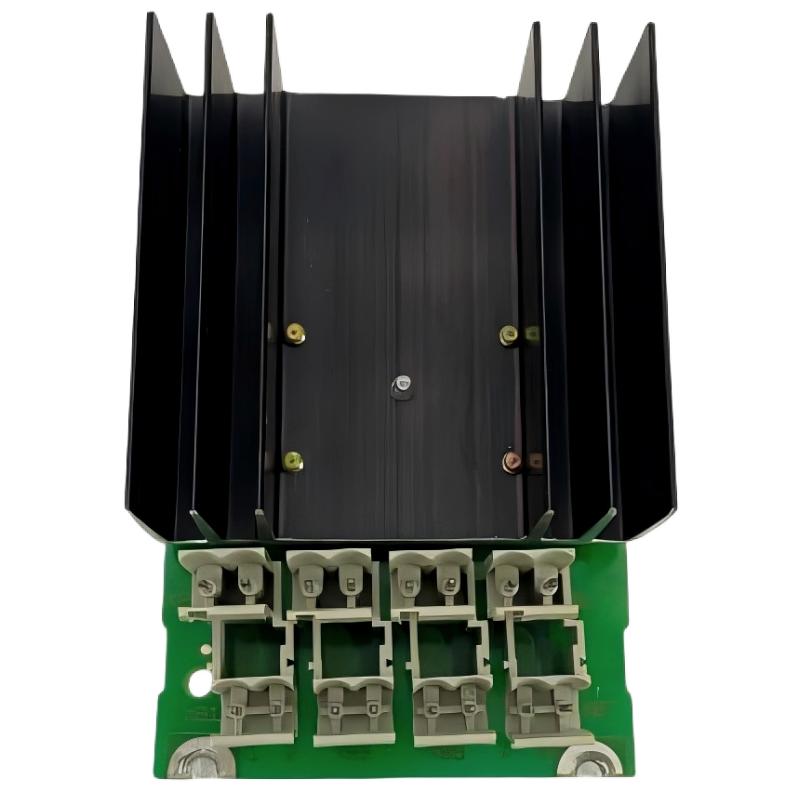 ABB SS110 3BSE007698R1 Voting Unit Installation Guide
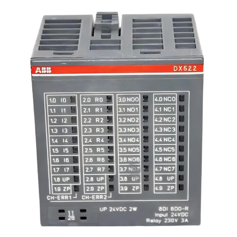 ABB DX522 1SAP245200R0001 Digital Input/Output Module Installation Guide
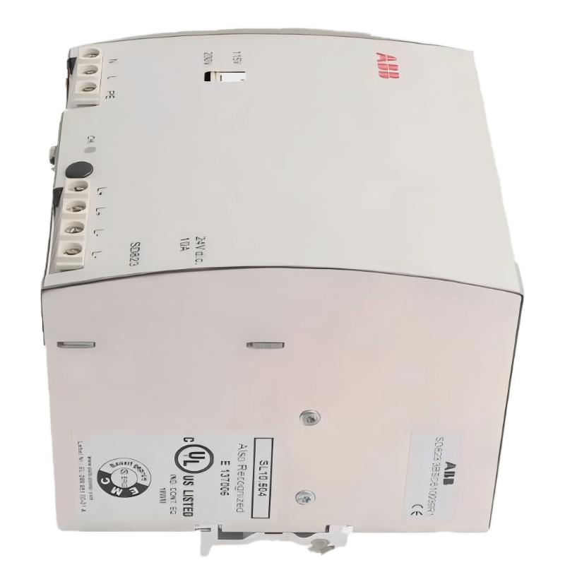 ABB SD823 3BSC610039R1 Power Supply Installation Guide