100% Original, Ready to Ship!

ABB 87TS01I-E GJR2368900R2313 Coupler Module Installation Guide
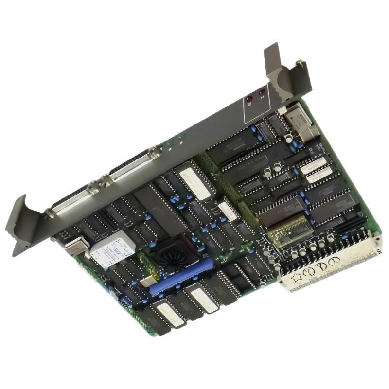 Table of Contents: ABB 87TS01I-E Coupler Module Installation
- Coupler Module Role and Application
- Installation Preparation and Compatibility
- Mounting and Interface Connections
- System Configuration and Commissioning
- Field Commissioning Example
- Installation FAQ
- Conclusion and Final Checks
ABB 87TS01I-E GJR2368900R2313 Coupler Module Role
A coupler module provides an interface between designated parts of an industrial control architecture. Its exact function depends on the equipment family, backplane design, communication interface, and approved system configuration. Before installation, confirm the application of the ABB 87TS01I-E GJR2368900R2313 against the relevant ABB documentation rather than assuming compatibility based on the coupler designation alone.
For maintenance engineers, the key objective is to establish a dependable connection without introducing wiring errors, incompatible hardware, or an unintended change to the existing control configuration.
ABB 87TS01I-E Coupler Module Installation Preparation
- Check the complete part number, including GJR2368900R2313, and record the available hardware revision.
- Compare the module with the approved bill of materials, rack layout, and system drawings.
- Verify the specified supply voltage, connector arrangement, interface type, and any termination requirements using the applicable technical documentation.
- Back up the current controller configuration and document existing module addresses or communication settings where applicable.
- Apply the site’s lockout/tagout procedure and isolate hazardous energy before handling the module.
- Use suitable ESD protection and inspect connectors for bent contacts, contamination, or mechanical damage.
Do not infer electrical ratings, pin assignments, or bus compatibility from appearance alone. If the correct installation manual is unavailable, resolve the documentation gap before energizing the assembly.
ABB 87TS01I-E Coupler Module Mounting and Connections
Mechanical installation should follow the specified rack or mounting arrangement. Check that the module is seated evenly, its retaining mechanism is engaged, and adjacent components do not obstruct ventilation or access to connectors.
- Confirm the equipment is in a safe, de-energized condition.
- Inspect the designated slot and connector for foreign material or damaged contacts.
- Align the module with the approved guide rails and insert it using the manufacturer’s prescribed method.
- Secure the module and connect only the cables identified in the system drawings.
- Verify cable routing, shielding, grounding, and termination against the actual interface specification.
- Perform a final visual inspection before restoring power under the site’s commissioning procedure.
A coupler that appears mechanically installed may still have poor electrical contact. Uneven seating, loose retaining hardware, and connector contamination are therefore worth checking before investigating software or communication settings.
ABB 87TS01I-E System Configuration and Commissioning
The commissioning objective is to verify that the installed module is recognized and behaves as expected within the approved control architecture. Use the documented startup sequence for the specific system instead of applying a generic PLC startup procedure.
- Confirm that supply conditions meet the specified limits.
- Check the module’s status indicators against the manufacturer’s indicator table.
- Verify that the controller or engineering workstation identifies the expected hardware, where supported.
- Review diagnostic messages, interface status, configured addresses, and bus termination settings where applicable.
- Test representative communication or data-transfer functions using an approved commissioning plan.
- Record the final status, configuration revision, and any outstanding alarms.
Commissioning checklist (pseudocode)

verify_part_number("87TS01I-E GJR2368900R2313")
verify_hardware_compatibility()
verify_supply_against_manual()
inspect_status_indicators()
check_system_diagnostics()
validate_approved_interface_configuration()
record_commissioning_results()
The commands above are illustrative checklist labels, not executable ABB diagnostic commands. Use the actual engineering tools and procedures supported by the installed system.
ABB 87TS01I-E Coupler Module Field Commissioning Example
Consider a representative maintenance scenario in which a replacement coupler is installed but the control system does not immediately report the expected interface status. Rather than replacing additional components, the engineer first compares the replacement part number and hardware revision with the approved configuration, then checks module seating, connector condition, supply measurements, and diagnostic records.
If the supply measurement is within the documented limits but the interface remains unavailable, the investigation should move to the applicable bus configuration, termination, addressing, and compatibility requirements. The actual cause must be established from observed evidence; no specific voltage, recovery time, or successful result should be assumed without recorded measurements.
ABB 87TS01I-E Coupler Module Installation FAQ
What should be verified before installing the ABB 87TS01I-E GJR2368900R2313?
Confirm the complete part number, hardware revision, approved slot, electrical requirements, interface compatibility, and applicable installation instructions.
Can the coupler be replaced while the control system is running?
Do not assume hot-swap support. Replacement should follow the equipment-specific procedure, including shutdown and isolation requirements unless the manufacturer explicitly approves live replacement for the installed configuration.
Why might a newly installed coupler fail to establish communication?
Possible causes include an incompatible revision, poor connector contact, incorrect interface configuration, wiring faults, missing termination, or a problem elsewhere in the control network.
Which diagnostic information should be recorded during commissioning?
Record the part and revision, status indicators, measured supply values, diagnostic messages, relevant configuration settings, and the results of approved interface tests.
ABB 87TS01I-E Coupler Module Installation Conclusion
Successful installation of the ABB 87TS01I-E GJR2368900R2313 Coupler Module depends on verified compatibility, correct mechanical seating, documented electrical connections, and evidence-based commissioning. Treat the approved system drawings and manufacturer documentation as the authority for pinouts, ratings, configuration settings, and diagnostic procedures. A documented baseline makes future troubleshooting more efficient and reduces the risk of unnecessary component replacement.
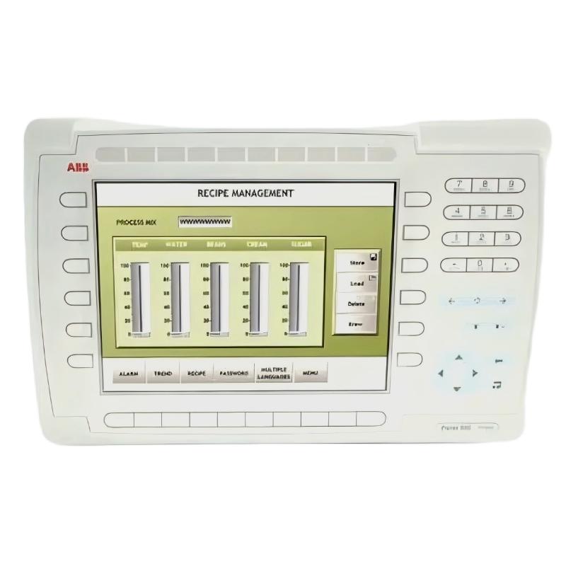 ABB PP845 3BSE042235R1 Operation Panel Installation Guide
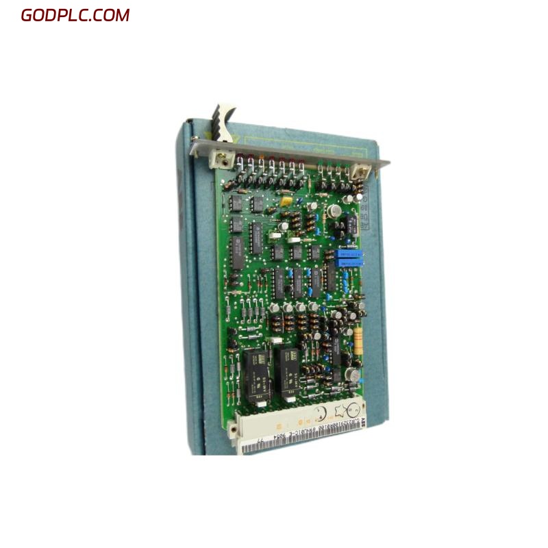 ABB 89NU01E Safety Relay Installation Guide
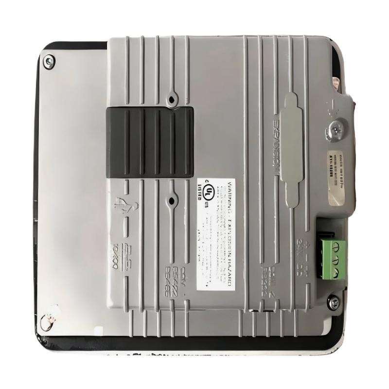 ABB PP825 3BSE042240R1 Operation Panel Installation Guide
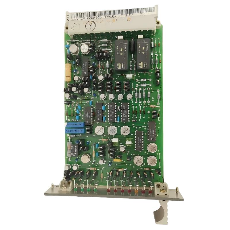 ABB 89NU01D-E GJR2329100R0100 Alarm Module Installation Guide