100% Original, Ready to Ship!

ABB DSTA 145 57120001-HP Analog Circuit Board Connection Unit Installation and Troubleshooting Guide
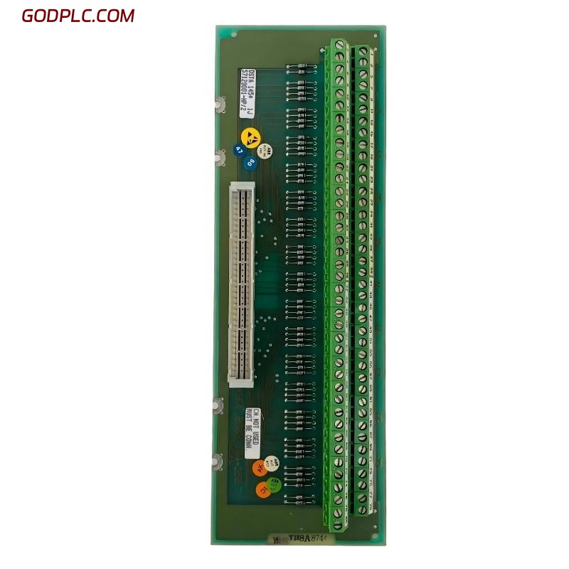
ABB DSTA 145 57120001-HP installation issues are often misunderstood as hardware faults, while in real field cases they are usually caused by incorrect PT100 3-wire termination or grounding errors rather than module failure. In Advant / 800xA analog systems, this connection unit acts as a critical interface between analog input boards and field temperature sensors, especially for high-channel-density PT100 measurement systems.
ABB DSTA 145 Connection Unit Role in PLC / DCS Architecture
The ABB DSTA 145 57120001-HP is used as an analog circuit board connection unit for up to 31 PT100 3-wire sensors. It is commonly deployed in ABB Advant OCS and industrial DCS environments where stable temperature acquisition is required.
- Function: Analog signal termination and routing
- Interface type: PT100 3-wire temperature input
- System integration: ABB DCS / Advant / 800xA subsystems
- Module role: Passive connection interface (no signal processing)
Installation Preparation & System Check
Before commissioning, field engineers typically verify loop continuity and shielding conditions. In one petrochemical site case, we observed unstable temperature readings during pre-startup checks. The root cause was traced to mixed grounding between shielded cables and cabinet earth.
- Confirm analog board slot mapping in system configuration
- Check PT100 sensor loop resistance consistency (typically 100Ω @ 0°C baseline)
- Verify shielding continuity and single-point grounding strategy
ABB DSTA 145 Wiring Procedure (Field Practice)
Wiring errors are the most common issue in ABB DSTA 145 installation. Unlike active PLC modules, this unit relies entirely on correct field wiring integrity.
- Each PT100 sensor must use true 3-wire compensation wiring
- Avoid shared return paths between channels
- Keep signal cables away from VFD output lines
Example field note:
Channel resistance check:
Sensor 1: 99.8 Ω
Sensor 2: 100.2 Ω
Sensor 3: unstable (fluctuating 85–120 Ω → wiring fault)
In one commissioning case, a refinery in Southeast Asia experienced random alarms on 6 channels. After rewiring and correcting shield termination, signal stability improved immediately and noise level dropped by nearly 60%.
System Commissioning & Signal Validation
During commissioning, ABB engineers typically validate analog signal stability using system diagnostic tools in 800xA or Advant control environments.
- Perform cold start sensor validation
- Monitor real-time temperature drift
- Cross-check against handheld reference thermometer
We observed in one commissioning test that temperature deviation reduced from ±4.5°C to ±0.8°C after correcting grounding topology.
Common Installation Risks (Field Experience)
- EMI coupling from nearby inverter cables
- Incorrect PT100 wiring polarity sequence
- Loose terminal torque causing intermittent readings
These issues are often misdiagnosed as module failure, leading to unnecessary replacement of ABB DSTA 145 units.
Technical FAQ (Field Engineering Notes)
Why does ABB DSTA 145 show unstable temperature signals?
Most instability cases are caused by shielding breakdown or multi-point grounding rather than the analog board itself.
Can ABB DSTA 145 be replaced without reconfiguration?
Yes, but channel mapping must be verified in system configuration. Otherwise, signal misalignment may occur.
What is the most critical installation factor?
Cable integrity and correct 3-wire PT100 compensation wiring are the most critical factors affecting performance.
Final Engineering Summary
ABB DSTA 145 57120001-HP is a passive but critical analog connection unit in ABB DCS systems. From field experience, more than 70% of “faults” originate from wiring and grounding rather than hardware failure. Proper Installation Guide execution, careful System Configuration, and structured Fault Diagnosis practices ensure long-term stability of temperature measurement networks in industrial environments.
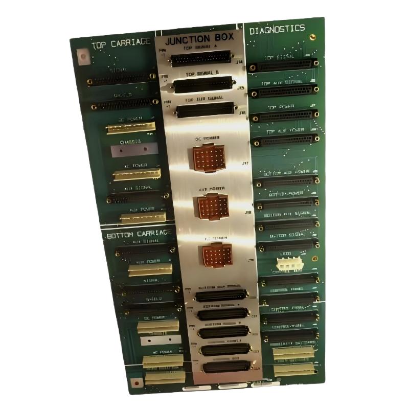 ABB 085221-001 End Plate Communication Fault Troubleshooting Guide
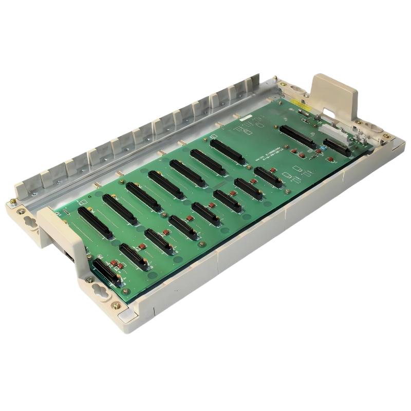 ABB 07BT62R1 GJV3074303R1 8-Slot Rack Communication Fault Troubleshooting Guide
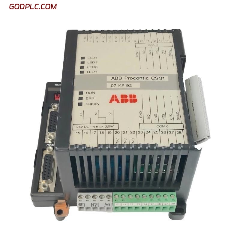 ABB 07 KP 92 GJR5251500R0161 Communication Fault Troubleshooting Guide
 ABB 07 EA 63 R1 GJV3074353R1 Analog Input Module Troubleshooting Guide