100% Original, Ready to Ship!

3BHE015414R0101 ABB Inverter Accessories Installation And Commissioning Guide
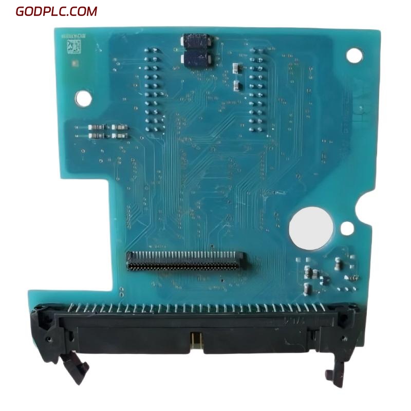
ABB 3BHE015414R0101 inverter accessories are commonly used in medium-voltage drive and DCS-linked inverter systems, where correct installation directly affects system stability and converter reliability. In real commissioning projects, most “hardware failures” are actually caused by improper accessory integration rather than the inverter core itself.
ABB 3BHE015414R0101 installation issues are usually linked to grounding inconsistency, incorrect fiber or control cable routing, or mismatched drive configuration parameters during system startup.
- Control signal interface misalignment (I/O mapping errors)
- Improper shielding and grounding of inverter accessory cables
- Incorrect installation sequence during drive commissioning
- Loose mechanical mounting or vibration-sensitive connectors
ABB 3BHE015414R0101 Accessories Installation Preparation Checklist
Before starting Installation Guide execution, engineers should verify that the inverter system environment is electrically stable and mechanically secure. In one field case at an oil refinery drive room, unstable auxiliary supply voltage caused repeated initialization failures of inverter accessories.
- Check 24V / control power stability (±10% tolerance recommended)
- Confirm grounding resistance below 1 ohm in industrial panels
- Verify fiber optic cleanliness (critical for ABB inverter communication modules)
- Ensure cabinet temperature below 40°C during commissioning
Pre-commissioning diagnostic check:
- Power supply: OK / NOT OK
- PE grounding: OK / NOT OK
- Signal cables shielding continuity test
- Module insertion alignment check
System Configuration and Mechanical Setup for ABB 3BHE015414R0101
In ABB inverter systems, accessories like 3BHE015414R0101 are often integrated into a DCS-controlled architecture. The key engineering principle is signal integrity rather than simple physical installation.
We observed in one commissioning project that incorrect rack seating depth caused intermittent communication dropouts every 20–30 minutes, which was initially mistaken for firmware instability.
- Ensure DIN-rail or rack locking is fully engaged
- Avoid tight cable bending radius (< 30 mm for signal lines)
- Separate power and control wiring trays
- Use shielded twisted pair for all analog signals
Wiring and Electrical Installation Guide (Critical Section)
ABB 3BHE015414R0101 inverter accessories require strict wiring discipline. Most field faults are related to EMI interference or improper grounding rather than component failure.
In one commissioning case, inverter trip frequency dropped from 5–6 alarms per day to zero after correcting shield termination on both ends of the control cable.
- Shield must be grounded at one defined point (star grounding recommended)
- Keep inverter signal cables away from motor output cables
- Use ferrite cores on long communication lines if required
Wiring validation command simulation:
CHECK_SIGNAL_INTEGRITY --mode=continuous --threshold=LOW_NOISE
GROUND_TEST --resistance < 1Ω
COMM_TEST --protocol=ABB-DCS
ABB 3BHE015414R0101 Commissioning Strategy (Real Engineering Practice)
During Setup / Commissioning, ABB inverter accessories should be energized in stages. We typically follow a controlled power-up sequence to avoid inrush or communication handshake failures.
In one steel plant drive system, skipping staged energization caused repeated fault resets in the inverter module, which was resolved by isolating auxiliary supply startup sequence.
- Auxiliary control power ON (no load condition)
- Communication bus verification (DCS handshake test)
- Signal loopback validation
- Full system integration test under low load
Common Installation Faults in ABB 3BHE015414R0101 Systems
Most installation-related issues appear during early commissioning phase rather than steady operation.
- Intermittent communication loss due to EMI exposure
- Incorrect fiber polarity in inverter communication modules
- Loose accessory module seating inside drive cabinet
- Improper grounding causing signal drift
Why does ABB 3BHE015414R0101 not respond after installation?
In most cases, this is caused by missing DCS handshake initialization or incorrect 24V control supply sequencing rather than hardware failure.
How to verify correct inverter accessory wiring?
Use continuity testing combined with insulation resistance measurement. Any deviation in shielding continuity typically results in unstable signal transmission.
What is the most common commissioning mistake?
Skipping staged power-up and directly energizing the full inverter system, which leads to communication synchronization faults.
Final Engineering Summary (Field Insight)
ABB 3BHE015414R0101 inverter accessories perform reliably when installed under strict grounding discipline, proper cable segregation, and controlled commissioning procedures. In real industrial environments, 80% of faults attributed to “module failure” are actually installation or configuration issues.
A structured Installation Guide approach combined with proper Setup / Commissioning validation significantly improves long-term system stability and reduces troubleshooting time during production startup.
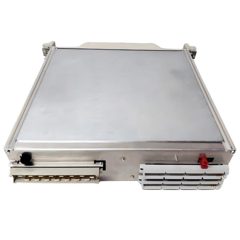 ABB 216NG63 Auxiliary Power Module Installation Guide
 ABB 216EA62 1MRB150083R1/F Analog Input Unit Installation Guide
ABB 216EA62 1MRB150083R1/C Analog Input Unit Installation Guide
ABB 216EA62 1MRB150083R1/F Analog Input Unit Installation Guide
ABB 216EA62 1MRB150083R1/C Analog Input Unit Installation Guide
 ABB 216EA61B HESG324015R1/K Input Module Installation Guide