
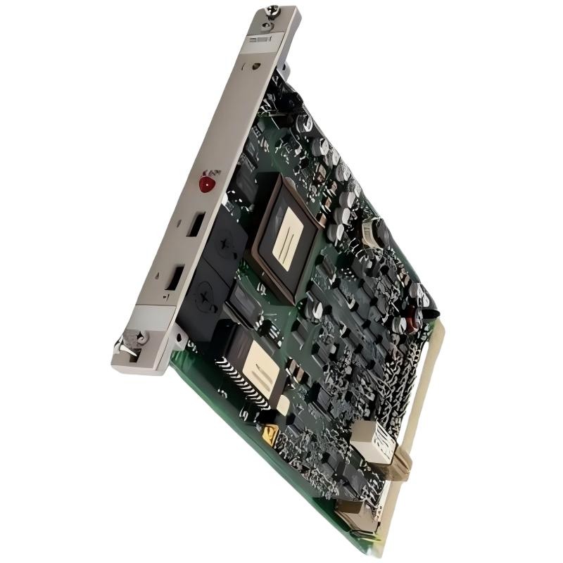
ABB 70EI05A-E HESG447427R1 Input Module Troubleshooting Guide
ABB 70EI05A-E HESG447427R1 troubleshooting should begin with the measured speed signal, not with immediate replacement of the module. When a Procontrol speed channel shows signal loss, unstable frequency, incorrect speed, or intermittent alarms, the fault may originate from the sensor, cable, grounding, configuration, or input electronics. A structured Fault Diagnosis therefore follows the signal from the rotating machine toward the controller.
ABB 70EI05A-E HESG447427R1 PLC and DCS Fault Symptoms
Typical symptoms associated with a problematic ABB 70EI05A-E speed input channel include a zero-speed indication while the machine is rotating, unstable speed values, intermittent signal-loss alarms, implausible frequency readings, or disagreement between the Procontrol indication and an independent speed reference.
- Speed indication suddenly drops to zero.
- Speed value fluctuates without a corresponding mechanical change.
- Input frequency disappears intermittently.
- Speed indication remains consistently higher or lower than the reference.
- Fault alarms appear during acceleration or deceleration.
- The problem occurs only when nearby electrical equipment is operating.
The timing of the symptom is particularly useful. A fault that appears only during acceleration requires a different investigation from a channel that is permanently dead.
ABB 70EI05A-E Fault Diagnosis Logic
The most effective Troubleshooting approach is to divide the signal path into four sections: mechanical sensor, field cable, ABB 70EI05A-E input stage, and controller interpretation. Test each section independently instead of changing several components at once.
- Confirm actual shaft movement using an independent reference.
- Verify that the sensor generates a pulse signal.
- Check whether the same signal reaches the cabinet termination.
- Confirm that the Input Module recognizes the expected frequency.
- Compare the module result with the controller’s configured scaling.
This approach is especially useful on older DCS installations because several decades of field modifications can make wiring drawings less reliable than direct measurement.
ABB 70EI05A-E HESG447427R1 Speed Signal Analysis
A speed input fault should be treated as a signal-quality problem until measurements prove otherwise. If the sensor generates pulses correctly but the controller reports zero speed, move the investigation toward the cable termination, module channel, or System Configuration.
If the measured pulse frequency is correct but the displayed speed is wrong by a consistent factor, investigate the configured pulses-per-revolution value or other application scaling before replacing hardware.
For example, if an independent reference indicates 1,500 r/min and the sensor arrangement generates 60 pulses per revolution, the expected pulse frequency can be calculated from the mechanical arrangement. A substantial difference between calculated frequency and measured frequency points toward the field signal path rather than the display logic.
ABB 70EI05A-E Common Speed Input Fault Causes
- Weak or deteriorated speed sensor output.
- Damaged or aged field wiring.
- Loose terminal connections.
- Incorrect cable shielding or grounding.
- Electromagnetic interference from power equipment.
- Incorrect pulse-per-revolution configuration.
- Incorrect rack or channel configuration.
- Input-stage degradation within the module.
Do not rank these causes solely by probability. The measured symptom should determine the next test. For example, a frequency value that suddenly becomes zero while the sensor output remains healthy is a different diagnostic path from a frequency value that changes continuously with electrical interference.
ABB 70EI05A-E Troubleshooting Diagnostic Commands
The following pseudo commands represent an engineering diagnostic sequence rather than vendor-specific software commands. They can be adapted to the available Procontrol maintenance tools and plant procedures.
# Fault Diagnosis logic
READ MODULE_STATUS
READ CHANNEL_STATUS
MEASURE SENSOR_OUTPUT
MEASURE CABINET_INPUT
COMPARE PULSE_FREQUENCY
CHECK SYSTEM_CONFIGURATION
COMPARE_REFERENCE_SPEED
TRACE_FAULT_LOCATION
Record the result of each measurement. Changing the module and the sensor at the same time destroys useful diagnostic evidence and can make intermittent faults harder to reproduce.
ABB 70EI05A-E HESG447427R1 Troubleshooting Case
In one field investigation, a speed channel intermittently indicated zero during operation. The first observation suggested an Input Module failure because the alarm was associated with the Procontrol channel. However, the engineering team compared the controller value with an independent speed indication before removing the card.
The independent reference showed that the shaft continued to rotate normally. The sensor signal was then checked and found to be present at the machine. At the cabinet, however, the pulse waveform showed intermittent disturbance. Inspection of the cable route found the speed-signal cable positioned alongside a high-energy power circuit.
After correcting the cable routing and restoring the intended shielding arrangement, the intermittent signal-loss symptom disappeared during repeated acceleration and steady-state tests. The ABB 70EI05A-E was therefore not replaced unnecessarily.
This case illustrates an important Fault Diagnosis principle: a DCS alarm identifies where the abnormal condition was detected, not necessarily where the physical fault originated.
ABB 70EI05A-E Input Module Repair and Recovery Strategy
If field wiring, sensor output, and System Configuration have been verified, the input module itself becomes a stronger suspect. Before installing a replacement, document the existing module identification, rack position, wiring arrangement, and observed fault condition.
- Record the original module model and part number.
- Verify the replacement is the correct hardware variant.
- Inspect connectors for contamination or mechanical damage.
- Follow the plant isolation procedure before removing hardware.
- Restore the module using the approved rack and configuration documentation.
- Repeat the same measurements used during the original diagnosis.
For legacy automation hardware, board-level repair should only be performed by personnel with suitable electronic test capability and authorization. A visually clean circuit board does not prove that its signal-conditioning or counting circuitry is healthy.
ABB 70EI05A-E Fault Recovery Verification
Successful recovery requires more than a returned speed indication. Run the channel through the operating conditions that originally exposed the fault. If the problem occurred during acceleration, reproduce acceleration. If it appeared when a large motor started, verify the signal during a comparable electrical event when safe to do so.
- Confirm stable sensor output.
- Confirm stable cabinet-side signal.
- Confirm valid module channel status.
- Compare calculated speed with the independent reference.
- Check associated alarms and protection logic.
- Document the final measured condition.
ABB 70EI05A-E HESG447427R1 Troubleshooting FAQ
Why does the ABB 70EI05A-E show zero speed while the machine is running?
Possible causes include loss of sensor output, an open or damaged cable, poor termination, signal interference, incorrect configuration, or an input-channel problem. The sensor signal should be measured before concluding that the module has failed.
How can an engineer distinguish a sensor fault from an Input Module fault?
Measure the signal at the sensor and then at the cabinet input point. If the signal is already missing at the sensor, investigate the sensor or mechanical target. If the signal is healthy at the sensor but degraded before reaching the module, investigate the field wiring. If the correct signal reaches the module but the channel remains incorrect, the module or configuration becomes a stronger suspect.
Why can electromagnetic interference create an intermittent speed fault?
Speed inputs depend on accurate pulse detection. Electrical interference can introduce false transitions or obscure valid transitions, particularly when signal cables are routed near high-current switching equipment.
Can incorrect System Configuration cause a stable but incorrect speed value?
Yes. A wrong pulse-per-revolution value or application scaling parameter can produce a stable indication that does not represent the actual shaft speed.
Should the ABB 70EI05A-E be replaced immediately after a signal-loss alarm?
No. A signal-loss alarm identifies an abnormal input condition but does not by itself prove hardware failure. Sensor output, cable integrity, grounding, configuration, and channel behavior should be checked first.
What is the most useful measurement during ABB 70EI05A-E troubleshooting?
The most useful measurement depends on the symptom, but comparing actual shaft speed, sensor pulse frequency, cabinet-side signal, and controller indication provides a strong basis for locating the fault.
ABB 70EI05A-E HESG447427R1 Troubleshooting Conclusion
Effective ABB 70EI05A-E HESG447427R1 Troubleshooting is a process of locating where the speed signal stops being correct. Sensor condition, cable integrity, electrical interference, System Configuration, and module performance should be separated during Fault Diagnosis. When measurements are taken in sequence, unnecessary module replacement is reduced and the actual failure mechanism becomes much easier to identify.



