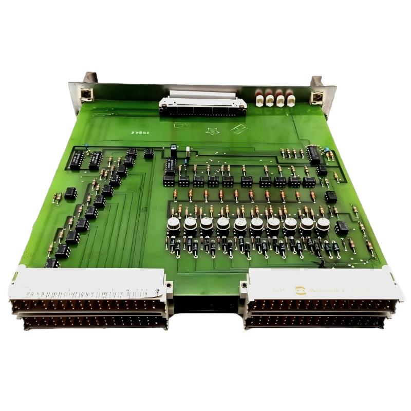
Diagnosing ABB PM572 CPU Module Faults in AC500 PLC Systems
ABB PM572 1SAP130200R0200 CPU module faults should be investigated by separating power problems, application errors, serial communication failures, and hardware-related issues. On the AC500 PLC platform, an unresponsive HMI, missing field data, or unexpected machine stop does not automatically indicate a failed CPU. A structured Fault Diagnosis process helps identify the actual failure point before components are replaced or the application is restarted.
The PM572 is a 24 V DC AC500 processor module with 128 kB program memory, two configurable RS-232/RS-485 interfaces, an FBP interface, and a diagnostic display. Its lack of integrated Ethernet is also important when investigating communication complaints involving Ethernet-based supervisory systems.
ABB PM572 Troubleshooting Contents
- Recognizing fault patterns
- A systematic diagnostic approach
- Power and startup fault diagnosis
- RS-232/RS-485 communication troubleshooting
- Application recovery and CPU replacement
- Technical troubleshooting FAQ
- Final fault assessment
ABB PM572 PLC Fault Symptoms and Failure Patterns
Start with the symptom observed by the operator, then determine whether the failure affects the whole controller or only one function. The distinction is critical because a communication fault may leave the PLC application running, while a power interruption can affect the entire control system.
- CPU appears inactive: Check the incoming supply, terminal connections, diagnostic display, and status indicators.
- PLC runs but field data is missing: Investigate the relevant serial link, FBP-connected equipment, I/O configuration, and device status.
- Communication drops intermittently: Inspect cable routing, electrical interference, shielding, connectors, and protocol timeouts.
- Application stops or behaves unexpectedly: Review controller diagnostics, application logic, task behavior, and recent configuration changes.
- Fault returns after a restart: Determine whether the underlying cause remains present instead of repeatedly resetting the controller.
Field experience suggests that the order of investigation matters: establish whether the CPU is powered and operating before focusing on higher-level communication or application behavior.
ABB PM572 Fault Diagnosis: Follow the Evidence
Use a divide-and-isolate method. First establish the controller’s operating state, then check the affected communication path or I/O subsystem. Compare current measurements with documented operating limits and the machine’s normal baseline.
- Record the exact diagnostic display, LED states, and operator alarm before changing anything.
- Confirm whether the CPU remains in its expected operating mode.
- Measure the supply at the designated terminals and check for voltage fluctuations during load changes.
- Determine whether all I/O devices are affected or only one station or channel.
- Review the latest project, parameter, wiring, and maintenance changes.
- Compare the observed fault with the applicable ABB diagnostic documentation.
ABB PM572 diagnostic checklist — illustrative pseudocode

RECORD cpu_display_and_status
CHECK 24V_DC_supply_at_designated_terminals
CHECK controller_operating_state
IF cpu_operational THEN
    INSPECT affected_IO_and_communication_path
    VERIFY serial_protocol_and_device_parameters
ELSE
    INVESTIGATE power, startup, configuration, and CPU diagnostics
END_IF
VERIFY root_cause_before_reset_or_replacement
This is diagnostic pseudocode for an engineer’s checklist, not an executable ABB command set. Use the controller’s supported engineering software and documented diagnostic functions for actual tests.
ABB PM572 Power Supply and Startup Troubleshooting
When the PM572 fails to start normally, begin at the power source rather than immediately replacing the processor. A supply can show a normal reading without load and still fall outside its permitted range when connected equipment starts.
- Measure the DC supply at the designated system terminals with an appropriately rated meter.
- Inspect terminal tightness, conductor condition, polarity, and the condition of the compatible terminal base.
- Check whether the supply dips during contactor operation or other high-load events.
- Review diagnostic indications and compare them with the specific hardware manual.
- Inspect the controller’s mounting and connections only after isolating power according to the approved procedure.
For example, a reading that falls from 24.1 V DC to 21.8 V DC during a switching event would justify investigating the power supply, wiring resistance, and transient load. These figures are illustrative diagnostic values, not a verified PM572 fault record or an ABB acceptance limit. The applicable module and system specifications determine whether a measured value is acceptable.
If supply stability is confirmed, proceed to the startup diagnostics, application compatibility, firmware requirements, and hardware configuration. Avoid repeated power cycling when the cause of the startup fault is unknown.
ABB PM572 RS-232/RS-485 Communication Fault Troubleshooting
When the PLC continues executing its application but a connected device stops responding, investigate the communication path before concluding that the CPU is defective. The PM572’s two serial interfaces can be configured for supported communication functions, but each connection must use the correct electrical interface and protocol settings.
RS-232 connection failures
Check the approved cable pinout, transmit and receive connections, signal reference, and device settings. Verify that the connected device supports the selected protocol and that the programming or communication interface is configured correctly.
RS-485 intermittent communication
Inspect differential-pair polarity, network topology, termination, biasing, cable length, and grounding arrangements. Look for long parallel runs beside motor cables, damaged shield connections, or poorly secured terminals that may cause intermittent errors.
Modbus or CS31 data inconsistencies
Verify the configured protocol, station address, baud rate, parity, data format, register or data mapping, and timeout settings. A responding device can still produce incorrect values when the mapping or data interpretation is wrong.
In an illustrative diagnostic scenario, a serial device that responds correctly at 9,600 baud but produces repeated timeouts after a cabinet modification should prompt a comparison of wiring, grounding, and parameter changes. Confirm the fault with a known-good cable or controlled test configuration before changing multiple settings simultaneously.
ABB PM572 PLC Application Recovery and CPU Replacement Decisions
When power and external communication checks pass, investigate the application and hardware configuration. Check whether a recent download, project revision, firmware change, or I/O expansion introduced a mismatch. Use the supported Automation Builder environment and preserve the existing application and diagnostic evidence before performing recovery actions.
- Back up the available application and record the current controller configuration.
- Compare the installed hardware with the project configuration.
- Review build messages, controller diagnostics, and relevant application changes.
- Check communication and I/O behavior independently where the approved test procedure permits.
- Restore a known-good application only after confirming compatibility and authorization.
- Consider CPU replacement only when the evidence supports a hardware failure or other documented replacement criterion.
Before replacing the PM572, verify the exact order code, compatible base, project compatibility, firmware requirements, and backup availability. A replacement module may require configuration and application restoration; physical installation alone does not guarantee that the machine will return to its previous operating state.
Any restart, download, output test, or hardware replacement must follow the plant’s isolation, process-safety, and change-control procedures. Never bypass safety interlocks to test whether a PLC fault has cleared.
ABB PM572 CPU Module Troubleshooting FAQ
Why does the ABB PM572 PLC fail to start?
Possible causes include an unsuitable or unstable power supply, incorrect connections, startup diagnostics, incompatible configuration, or a hardware fault. Record the displayed diagnostic information and verify supply conditions before deciding on corrective action.
Why does the PM572 communicate with one device but not another?
Check the interface type, cable pinout, protocol settings, station address, and device-specific parameters. Different devices may require different serial configurations even when connected to the same controller model.
Can the PM572 connect directly to an Ethernet network?
The 1SAP130200R0200 PM572 does not include an integrated Ethernet port. Determine whether a compatible communication module or another supported architecture is required for the intended network connection.
What should be checked when RS-485 communication is intermittent?
Inspect differential-pair polarity, termination, biasing, shielding, grounding, cable routing, connectors, and serial parameters. Change one variable at a time and record the results so that the root cause can be identified.
Does a communication timeout mean the CPU needs replacement?
No. A timeout can originate from cabling, the remote device, protocol configuration, electrical interference, or application logic. Confirm that the CPU itself has a relevant diagnostic fault before considering replacement.
How can a PM572 application be restored after a fault?
Use an approved, compatible project backup and the supported engineering software. Verify the CPU type, firmware, hardware configuration, and safety conditions before downloading or restarting the application.
Should the PLC be reset as the first troubleshooting action?
No. Capture the current fault evidence first. A reset may clear useful diagnostic information without correcting the underlying problem, and restarting a controller can affect the process or machine.
When is professional hardware inspection necessary?
Escalate when supply and wiring checks are satisfactory but documented CPU diagnostics persist, the module shows signs of physical damage, or the fault cannot be isolated using approved tests. Inspection and replacement should be performed by qualified personnel.
ABB PM572 Troubleshooting and Fault Diagnosis Summary
Effective ABB PM572 troubleshooting depends on evidence-based isolation rather than immediate resets or module replacement. Confirm power integrity, interpret the diagnostic display, separate CPU faults from serial communication problems, and verify the application and System Configuration. Record measurements, compare them with applicable ABB specifications, and validate recovery under controlled conditions.
The scenarios and sample measurements in this guide are illustrative engineering examples, not independently verified field incidents. For confirmed fault codes, electrical limits, terminal assignments, and repair decisions, consult the official ABB documentation for the exact PM572 hardware and installed system.