100% Original, Ready to Ship!

ABB 88UM01A GJR2329800R0100 Troubleshooting Guide: Bus Communication And Module Fault Diagnosis
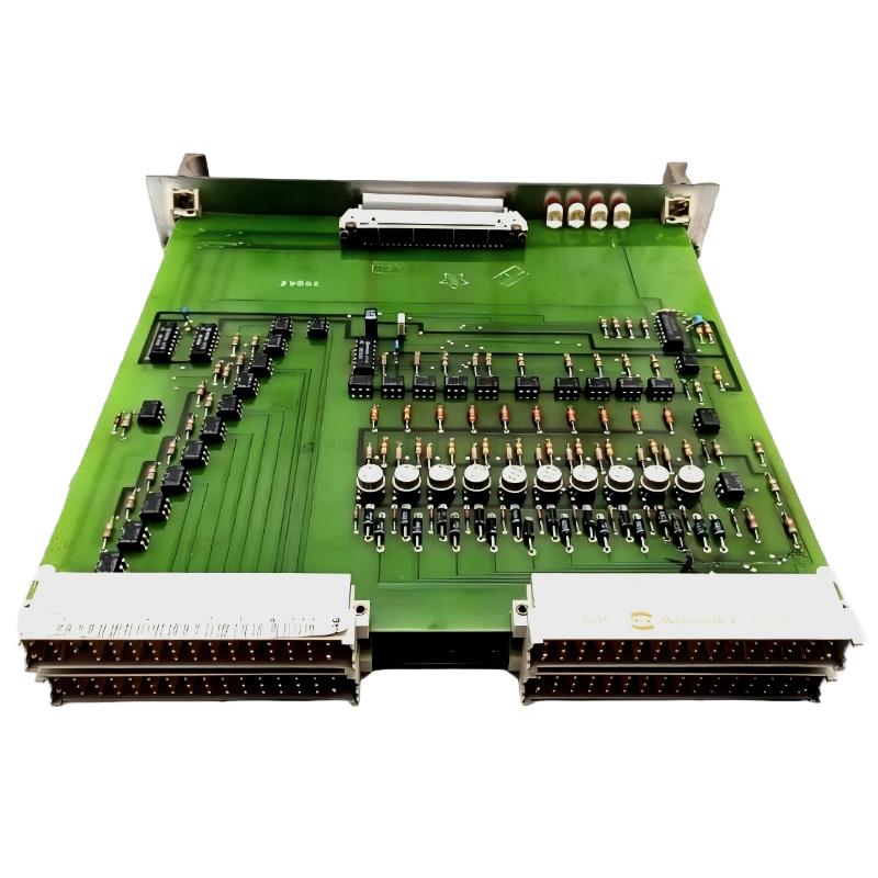
ABB 88UM01A GJR2329800R0100 Bus Control Module troubleshooting should begin with the observed fault, controller diagnostic records, and the condition of the bus connection. When a monitoring module is not recognized, communication becomes unstable, or system status differs from expectations, engineers should isolate the fault systematically before replacing hardware. Correct Fault Diagnosis requires distinguishing configuration errors and external communication problems from a possible internal module failure.
ABB 88UM01A Bus Control Module Fault Symptoms
The first task is to define exactly what has changed. A module that is absent from the controller configuration requires a different investigation from one that is recognized but reports abnormal status.
- Module recognition failure: The controller does not display the expected module or reports a configuration mismatch.
- Bus communication interruption: Communication-related diagnostics appear, or the expected data exchange stops.
- Intermittent operation: The fault appears and clears without a deliberate configuration change.
- Unexpected monitoring status: The displayed status does not agree with the expected operating condition.
- Repeated diagnostic events: Similar alarms recur after a reset or restart.
These symptoms are general troubleshooting categories, not confirmed fault codes specific to the ABB 88UM01A. Always use the diagnostic definitions available for the actual controller and module revision.
ABB 88UM01A Troubleshooting: Establish the Fault Pattern
Before disconnecting cables or restarting equipment, collect the evidence that can disappear after a reset. Record the first alarm, subsequent events, controller status, operating conditions, and whether other devices on the same bus are affected. A fault limited to one module suggests a different investigation from a communication failure affecting several devices.
Separate Module Faults from Bus Network Faults
If multiple devices lose communication at the same time, investigate shared elements such as the bus segment, power supply, network interface, grounding, and controller configuration. If only the ABB 88UM01A is affected, inspect its local connection, configuration assignment, and hardware condition. This comparison narrows the search without assuming that the module itself is defective.
ABB 88UM01A Fault Diagnosis Using a Structured Investigation
- Preserve the evidence. Export or record diagnostic messages and the event sequence before clearing alarms.
- Check system recognition. Compare the configured hardware with the installed part number and the supported system architecture.
- Inspect physical connections. Under the approved isolation procedure, examine connectors, cable terminations, and visible signs of damage.
- Review bus integrity. Compare cable routing, shielding, grounding, topology, and termination with the approved drawings.
- Validate configuration. Check applicable hardware assignments and communication parameters for unintended changes.
- Retest under controlled conditions. Verify whether the original symptom returns and record the result.
ABB 88UM01A Bus Communication Troubleshooting Commands
The following pseudocode illustrates how an engineer might organize a diagnostic review. It is not an executable ABB command set and does not represent native syntax for a specific controller.
BEGIN DIAGNOSTIC REVIEW
  Record module identity and current status
  Capture controller event history
  Compare configured and installed hardware
  Review bus communication diagnostics
  Inspect approved wiring and connection points
  Apply one corrective action at a time
  Repeat the same functional test
  Document the final status
END DIAGNOSTIC REVIEW
Use the supported engineering software and manufacturer-defined procedures for actual diagnostics. Do not run undocumented commands or change bus parameters simply to see whether the fault disappears.
Common Causes of ABB 88UM01A Module Communication Faults
- Incorrect System Configuration: The installed hardware does not match the configured hardware or supported system arrangement.
- Loose or damaged connections: A connector or cable termination may prevent reliable communication.
- Electrical interference: Inadequate separation from noisy conductors or improper shielding may affect susceptible communication interfaces.
- Grounding or termination problems: The installation may not follow the requirements of the actual bus interface.
- Power-related problems: An abnormal supply condition may affect the module or associated communication equipment.
- Hardware damage: Internal failure remains a possibility after external connections, configuration, and related equipment have been checked.
These are general industrial automation fault possibilities. They should be treated as investigation paths, not as a confirmed list of model-specific defects.
ABB 88UM01A Field Troubleshooting Example
In an illustrative investigation, a bus control module repeatedly disappears from the controller diagnostics. The engineer initially suspects a defective module but finds that other devices on the same communication segment also show interruptions. This changes the investigation from an immediate module replacement to a review of shared bus connections, power conditions, and network configuration. After checking the approved drawings and correcting an identified installation issue, the engineer repeats the original test and compares the event history.
This example demonstrates a practical Fault Diagnosis method; it is not a verified ABB service case, and no specific measured result is claimed. In a real service report, include the actual fault timestamps, measured electrical values, devices affected, corrective action, and post-repair verification results.
ABB 88UM01A Module Repair and Recovery Decisions
Repair decisions should follow the evidence. Correct an identified configuration or connection issue before considering component replacement. If the fault persists after external causes have been excluded, verify the module against the manufacturer’s diagnostic and service criteria. Do not open, modify, or repair internal electronics unless authorized procedures and suitably qualified personnel are available.
After recovery, confirm stable module recognition, expected communication behavior, and the absence of recurring diagnostic events during an appropriate observation period. Record the final configuration and retain the original fault history for future maintenance.
ABB 88UM01A Troubleshooting FAQ
Why is the ABB 88UM01A not recognized by the controller?
Possible causes include hardware configuration mismatch, an incompatible system arrangement, poor connector engagement, or a module fault. Review the controller diagnostics and approved hardware documentation before replacing the module.
How can intermittent bus communication be investigated?
Correlate communication events with operating conditions and inspect the relevant connections, cable routing, shielding, grounding, and supported bus configuration.
Does a communication alarm prove that the module is defective?
No. A communication alarm indicates a problem detected by the system, but the root cause may be external wiring, another device, configuration, or the communication infrastructure.
When should the module be replaced?
Consider replacement only after the applicable diagnostic procedure supports a hardware fault and external causes have been reasonably excluded. Confirm replacement compatibility before installation.
Can restarting the controller solve the fault?
A restart may clear a temporary symptom, but it does not establish the root cause. Capture diagnostic evidence first and follow the site’s approved restart procedure.
How should a repaired module be validated?
Repeat the original functional test, verify module recognition and expected communication, monitor for recurring alarms, and document the results.
Conclusion: ABB 88UM01A Bus Control Module Fault Recovery
Effective ABB 88UM01A GJR2329800R0100 Troubleshooting depends on identifying the fault pattern, preserving diagnostic evidence, checking System Configuration, and separating bus-level issues from possible module failure. A disciplined investigation reduces unnecessary replacements and makes the recovery process easier to verify. Return the equipment to operation only after the applicable functional checks and site acceptance requirements have been satisfied.
General note: This article provides general industrial automation troubleshooting guidance. Exact fault codes, electrical limits, diagnostic commands, repair procedures, and replacement criteria must be verified against the applicable ABB documentation and installed control system. The field example is illustrative and must not be represented as a documented real-world repair.
 ABB PM572 1SAP130200R0200 CPU Module Troubleshooting Guide
 ABB 89AS30 GKWN000317R0100 Analog Signal Multiplier Troubleshooting Guide
 ABB PM510 3BSE000270R1 CPU Board Troubleshooting Guide
 ABB 89AR30/R0100 Relay Unit Troubleshooting Guide For Control And Protection Faults