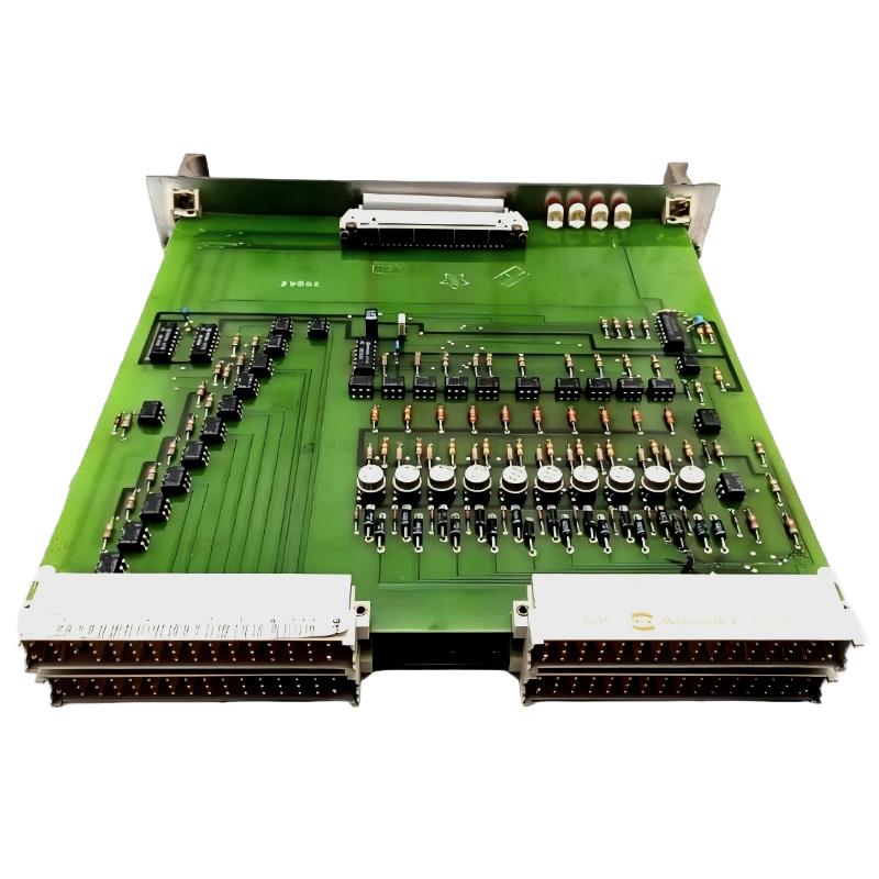
ABB 89AR30/R0100 Relay Unit Troubleshooting and Fault Diagnosis
ABB 89AR30/R0100 Relay Unit faults should be investigated by tracing the complete control path from the initiating command to the relay contact and final feedback signal. In a Procontrol P turbine control application, an unexpected permissive, missing status indication, or failure to change contact state does not automatically prove that the relay unit is defective. Control power, connector integrity, external wiring, interlocks, and downstream input circuits must be checked before hardware replacement is justified.
Contents of the ABB 89AR30/R0100 Fault Diagnosis Guide
- Recognizing Relay Unit Fault Symptoms
- A Practical Fault-Isolation Method
- Electrical Measurements and Signal Analysis
- Example of an Intermittent Relay Fault
- Repair and Recovery Decisions
- Troubleshooting FAQ
- Final Engineering Assessment
ABB 89AR30/R0100 Relay Unit Fault Symptoms
Fault symptoms should be recorded before any conductor is removed or any component is replaced. The timing and repeatability of a failure often provide more useful information than the initial alarm description.
- No contact transition: The initiating command changes, but the expected relay contact state does not.
- Missing feedback: The physical contact changes state, but the controller continues to display an incorrect status.
- Intermittent operation: The fault appears after vibration, temperature changes, maintenance activity, or repeated switching.
- Unexpected permissive status: The control logic does not receive the state required for the intended sequence.
- Repeated protective alarms: A relay-related signal changes unexpectedly, although the root cause may lie elsewhere in the circuit.
These symptoms are diagnostic categories rather than confirmed failure characteristics unique to the 89AR30/R0100. The actual fault indication depends on the host system and application logic.
ABB 89AR30/R0100 Fault Diagnosis: Trace the Signal Path
The most efficient troubleshooting approach separates the circuit into independently verifiable sections. Begin with the control-system indication, then establish whether the command exists electrically, whether the relay responds, and whether the resulting signal reaches its destination.
When the Command Is Missing
If the relay never receives the expected command, investigate the initiating logic, interlocks, controller output channel, and relevant supply conditions. Review event timestamps and sequence-of-events records where available. Do not replace the relay merely because its output remains inactive.
When the Command Is Present but the Contact Does Not Change
Verify the signal at the approved test point and compare the measured value with the specified operating limits. Then inspect the connector interface and the external contact circuit. If the command and supply are correct, but the expected contact transition remains absent under a valid test condition, an internal relay or connection fault becomes more plausible.
When the Contact Changes but Feedback Is Incorrect
Shift the investigation downstream. Check conductor continuity, terminal identification, receiving input-channel status, signal common, and the controller’s interpretation of the input. A correct physical contact state combined with incorrect software indication often points away from the relay itself.
ABB 89AR30/R0100 Electrical Measurements and Signal Analysis
Electrical measurements should be taken only by qualified personnel using the approved test procedure. Reference values must come from the relevant circuit drawings and component documentation; a generic voltage or resistance value cannot safely be assigned to every relay circuit.
- Identify the exact command and feedback terminals from the approved drawing.
- Measure the control signal under the specified operating condition.
- Compare the result with the documented nominal value and tolerance.
- Check the contact state using an appropriate method for the circuit design.
- Where permitted, isolate the relevant circuit before continuity or resistance testing.
- Compare the observed contact state with the controller’s recorded status.
Relay fault-isolation logic — illustrative pseudocode

IF command_is_absent:
    inspect_controller_logic_and_interlocks
ELSE:
    verify_control_signal_and_supply

IF command_is_valid AND contact_state_is_incorrect:
    inspect_connector_and_relay_circuit
ELSE IF contact_state_is_correct AND feedback_is_incorrect:
    inspect_downstream_wiring_and_input_channel

record_measurements
confirm_root_cause
perform_authorized_functional_test
This is illustrative diagnostic pseudocode, not a native Procontrol P command set. It must not be used as a substitute for the approved protection-system test procedure.
ABB 89AR30/R0100 Relay Unit: Intermittent Fault Investigation Example
In a hypothetical maintenance investigation, an operator reports that a relay-dependent status occasionally disappears even though the associated control command remains active. The first observation suggests a relay fault, but the engineer avoids making that assumption.
Event records are compared with the command status, and the circuit is inspected for loose terminations or connector problems. During an approved test, the engineer checks the signal at the relay input and then checks the resulting contact state. If both remain stable while the controller feedback fluctuates, the receiving input circuit and its wiring become the next investigation targets.
If the relay input itself becomes unstable, the investigation instead moves upstream toward the control output, supply, and connection points. This sequence distinguishes a real internal relay failure from an external signal problem without unnecessary component substitution.
The scenario is an engineering example, not a verified field report for this exact model. No measured values or repair outcome are presented as actual ABB service data.
ABB 89AR30/R0100 Relay Unit Repair and Recovery Decisions
Repair should follow the evidence obtained during Fault Diagnosis. Avoid opening or modifying the relay assembly unless the manufacturer’s service instructions explicitly permit it.
- Connector or termination defect: Correct the connection using the approved procedure, then repeat the relevant continuity and functional checks.
- Incorrect control signal: Resolve the upstream logic, interlock, or output-channel problem before retesting the relay.
- Feedback circuit fault: Repair the identified external wiring or receiving-channel issue and confirm that the displayed status matches the physical state.
- Suspected internal relay failure: Verify the command, supply, wiring, and contact behavior before arranging an approved replacement.
- Recurring or unexplained failure: Preserve event logs, measurements, hardware identification, and test conditions for specialist investigation.
After corrective action, verify all affected functions against the approved cause-and-effect matrix. Protection interlocks must not be bypassed to force a successful test, and return to service must follow the site’s authorization process.
ABB 89AR30/R0100 Relay Unit Troubleshooting FAQ
Why does the relay-dependent status remain inactive when a command is issued?
Possible causes include a missing control signal, an incorrect supply condition, a connector problem, a defective contact, or a downstream wiring fault. Trace the circuit in order before replacing the unit.
How can an internal relay fault be distinguished from a controller output fault?
Verify the controller command and measure the corresponding signal at the approved relay input point. A missing input indicates that the upstream circuit needs investigation; a valid input with an incorrect contact response supports further examination of the relay circuit.
Can a loose connector cause intermittent operation?
Yes. A degraded or poorly seated connection can interrupt a control or feedback signal intermittently. Inspect connector condition and retention under the equipment isolation procedure.
Should relay contacts be tested with an ohmmeter?
Only when the circuit has been safely isolated and the applicable procedure permits the test. Measuring resistance on an energized circuit can damage equipment and expose personnel to hazardous voltage.
What records are useful for diagnosing recurring relay faults?
Preserve alarm timestamps, command states, measured signal values, contact observations, controller diagnostics, hardware identification, and the results of each corrective action.
When should the ABB 89AR30/R0100 be replaced?
Replacement is justified when testing establishes a hardware defect or when the approved maintenance procedure requires replacement. Confirm that the replacement part and its configuration are suitable for the installed system.
Can a relay fault be cleared by resetting the controller?
A reset may clear a transient indication, but it does not establish the root cause. Determine why the signal became abnormal and verify stable operation before considering the fault resolved.
What must be checked before returning the system to service?
Verify correct wiring, expected relay contact states, downstream feedback, restored interlocks, and all affected functional tests. Document the results and obtain the required operational authorization.
Final Engineering Assessment of ABB 89AR30/R0100 Relay Unit Faults
Effective ABB 89AR30/R0100 Relay Unit Troubleshooting depends on evidence-based fault isolation rather than immediate component replacement. By separating the controller command, electrical input, relay contact, and feedback circuit, engineers can narrow the cause of a failure and select an appropriate corrective action. Accurate measurements, verified System Configuration, approved testing procedures, and complete maintenance records are essential to safe recovery. Where the available evidence does not establish an internal defect, further circuit-level investigation is preferable to an unsupported hardware diagnosis.