100% Original, Ready to Ship!

ABB 89AS30 GKWN000317R0100 Analog Signal Multiplier Troubleshooting Guide

ABB 89AS30 Analog Signal Multiplier Troubleshooting Guide
ABB 89AS30 GKWN000317R0100 analog signal multiplier faults should be diagnosed by comparing the input signal, all three independent function units, and their corresponding outputs. A missing or inaccurate signal does not automatically indicate a defective module. Incorrect jumper settings, excessive output load, wiring faults, supply problems, and downstream PLC or DCS scaling errors should be investigated before replacing the hardware.
ABB 89AS30 Fault Diagnosis: Start with the Signal Path
The ABB 89AS30-E/R0100 is designed for analog signal conversion and multiplication and contains three function units. Its documented signal options include 0–20 mA, 4–20 mA, and 0–10 V DC inputs, with current outputs configurable for supported ranges. The module uses a nominal 24 V DC supply, and its published transmission error is no more than 0.3% under specified operating conditions.
These specifications provide useful reference points during Troubleshooting, but the applicable datasheet and configured hardware determine the acceptance limits for an individual installation.
ABB 89AS30 PLC and DCS Fault Symptoms
- No output signal: The receiving PLC or DCS channel remains at zero or indicates a signal failure.
- Low or incorrect readings: The output does not match the expected response to a known input.
- One failed channel: One output path behaves differently while other function units continue operating.
- Unstable analog values: The displayed measurement fluctuates despite a steady process condition.
- Scaling discrepancy: The measured electrical signal is plausible, but the engineering value displayed by the control system is incorrect.
Record the exact symptom before making adjustments. Whether the problem affects all three function units or only one is often the first useful clue.
Investigating ABB 89AS30 Analog Signal Faults
Use the following fault-isolation logic to narrow down the cause without changing several variables at once.
- Confirm the source: Check the transmitter reading and measure the signal arriving at the module input using an appropriate instrument.
- Verify the configuration: Compare the input and output jumper positions with the approved wiring diagram and required signal ranges.
- Measure the supply: Check the nominal 24 V DC supply at the specified test points and compare the result with the manufacturer’s permitted limits.
- Inspect the affected output: Measure the output under the actual connected load and verify that the receiving circuit is wired correctly.
- Compare function units: If the design permits, compare equivalent input and output paths under the same controlled test conditions.
- Check the control system: If the electrical signal is correct, investigate the PLC or DCS input range, channel assignment, scaling, and alarm configuration.
Isolate the relevant circuits before moving jumpers or disconnecting conductors. Live measurements must follow approved electrical safety procedures.
Common Causes of ABB 89AS30 Output Failure
- Incorrect jumper configuration: The selected signal range does not match the connected transmitter or receiving input.
- Excessive output burden: The connected load exceeds the permissible output capability. The published maximum burden for current outputs is 1000 ohms under the specified conditions.
- Open circuit or loose termination: A broken conductor, loose terminal, or disconnected return path interrupts the signal.
- Incorrect supply or connection: The module does not receive the required supply at the designated terminals.
- Grounding or interference problems: Poor cable routing or inappropriate shield termination introduces noise into the measurement.
- Downstream configuration error: The module output is correct, but the receiving PLC or DCS interprets it using an incompatible range or scaling equation.
ABB 89AS30 Fault Diagnosis Using Measured Values
For a current-input configuration, compare the measured input current with the output values expected from the documented configuration. For example, a 12 mA input represents the midpoint of a 4–20 mA range. If a configured output is intended to reproduce that range, its expected value is 12 mA, subject to the specified accuracy and measurement uncertainty.
This is a diagnostic example, not a claim that a particular installed ABB 89AS30 has failed or that every configuration uses identical input and output ranges.
ABB 89AS30 troubleshooting checklist

READ source_instrument_value
MEASURE module_input
VERIFY configured_input_range
VERIFY output_jumper_positions
MEASURE output_1
MEASURE output_2
MEASURE output_3
CHECK output_load_and_wiring
COMPARE readings_with_expected_transfer_function
CHECK PLC_DCS_channel_scaling
DOCUMENT confirmed_root_cause
The commands are illustrative pseudocode for an engineering checklist. They are not native commands supported by the ABB 89AS30 hardware.
ABB 89AS30 Field Investigation: An Example of Fault Isolation
Consider a representative commissioning investigation in which a control-room operator reports that one analog value is lower than expected, while the other monitored values remain stable. The engineer first confirms the source transmitter reading and measures the module input. Both agree with the expected process value.
The engineer then measures the affected output and finds that it differs from the expected value. Inspection reveals that the output configuration does not match the receiving circuit’s required signal range. After verifying the approved drawings, isolating the circuit, and correcting the configuration, the engineer repeats the test at several input points.
Acceptance is based on recorded measurements meeting the applicable specification, not simply on the displayed value appearing normal. This is an illustrative fault-investigation scenario rather than a verified historical repair record for a specific ABB 89AS30 installation.
ABB 89AS30 Repair and Recovery Procedure
Repair should address the confirmed root cause rather than rely on indiscriminate component replacement.
- Correct wiring discrepancies and replace damaged conductors or terminals using approved parts.
- Restore the documented jumper configuration for the required input and output ranges.
- Resolve excessive load or incompatible receiving-circuit requirements.
- Correct PLC or DCS scaling only after confirming the actual electrical signal and engineering requirements.
- If the module continues to fail a controlled test, arrange bench testing by qualified personnel or an authorized repair provider.
Do not perform component-level repairs on energized equipment. Before returning the circuit to service, confirm signal behavior, alarm response, process interlocks, and any required operational approvals.
ABB 89AS30 Troubleshooting FAQ
Why does the ABB 89AS30 have no analog output?
Check the input signal, module supply, wiring continuity, jumper configuration, and output load. If these are correct, test the output using an approved procedure to determine whether the fault is internal to the module or external to it.
Why does one ABB 89AS30 output differ from the others?
Investigate the affected function unit’s wiring, output configuration, connected load, and receiving channel. Different output settings or loads may produce different readings even when the input is common.
Can incorrect jumper settings cause an analog signal error?
Yes. A mismatch between the selected signal range and the connected circuit can cause an incorrect or apparently saturated measurement. Verify the required settings against the product documentation before making changes.
What is the specified transmission error of the ABB 89AS30?
The published technical documentation specifies a transmission error of no more than 0.3% under its stated temperature and supply-voltage conditions. Use the applicable datasheet and test conditions when evaluating a measured discrepancy.
What should be checked when the PLC value is wrong but the output is correct?
Check the receiving analog input configuration, channel mapping, scaling formula, engineering-unit conversion, and any configured signal filtering. Avoid adjusting the multiplier if its electrical output already meets the required specification.
Can a high output load cause an inaccurate reading?
Yes. An output burden beyond the specified limit may prevent correct signal transmission. Check the total load, including the receiving input and any additional series resistance, against the module’s rated capability.
When should the ABB 89AS30 be replaced?
Consider replacement after wiring, supply, configuration, and load problems have been excluded and the module still fails a controlled test. Confirm the replacement’s full part number, hardware compatibility, and required configuration before installation.
How can recurring analog signal faults be prevented?
Maintain accurate wiring drawings, document jumper settings, inspect terminal condition, verify cable shielding, and periodically test signal paths against defined acceptance limits. Retain as-found and as-left readings to support future Fault Diagnosis.
General Overview of ABB 89AS30 Troubleshooting
Effective ABB 89AS30 GKWN000317R0100 Troubleshooting follows the signal from the source instrument through the multiplier to the receiving PLC or DCS. Confirmed measurements, correct jumper settings, appropriate output loading, and verified System Configuration are more reliable than replacing hardware based on symptoms alone. When a module fails documented acceptance tests after external causes have been eliminated, qualified bench diagnosis or replacement is the appropriate next action.
 ABB PM572 1SAP130200R0200 CPU Module Troubleshooting Guide
 ABB PM510 3BSE000270R1 CPU Board Troubleshooting Guide
 ABB 89AR30/R0100 Relay Unit Troubleshooting Guide For Control And Protection Faults
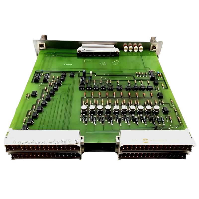 ABB 88UM01A GJR2329800R0100 Troubleshooting Guide: Bus Communication And Module Fault Diagnosis