
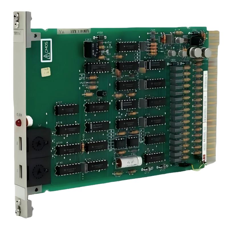
ABB 70EB01B-E Numeric Input Module Troubleshooting Guide
ABB 70EB01B-E HESG447005R2 input faults should be diagnosed from the field signal toward the controller, not by replacing the module first. A missing or unstable digital indication can originate from the field contact, 24 VDC supply, common return, terminal connection, cable, input channel or System Configuration. The module is documented as a 16-channel Procontrol P13 digital input device, so channel-by-channel comparison is a practical way to isolate the fault. :contentReference[oaicite:6]{index=6}
ABB 70EB01B-E Fault Diagnosis Path
ABB 70EB01B-E Numeric Input Module Fault Symptoms
Typical troubleshooting symptoms include one channel permanently OFF, one channel permanently ON, several channels changing together, an intermittent indication, or a field device showing the correct physical state while the DCS point remains unchanged.
- Input indication remains OFF with a confirmed active field signal.
- Input indication remains ON after the field device returns to normal.
- Several unrelated points change simultaneously.
- One channel behaves differently from adjacent channels.
- The physical voltage is correct but the controller point is incorrect.
- A signal becomes unstable during switching or nearby equipment operation.
ABB 70EB01B-E Troubleshooting Logic for Field Engineers
The most useful diagnostic question is not “Is the module bad?” but “Where does the signal stop being correct?” This changes the troubleshooting process from component replacement to evidence-based isolation.
IF FIELD_DEVICE = OFF
    CHECK FIELD_VOLTAGE

IF FIELD_DEVICE = ON AND SOURCE_VOLTAGE_OK
    CHECK TERMINAL_VOLTAGE

IF TERMINAL_VOLTAGE_OK
    CHECK MODULE_CHANNEL

IF MODULE_CHANNEL_OK AND DCS_POINT_WRONG
    CHECK SYSTEM_CONFIGURATION

IF MULTIPLE_CHANNELS_FAIL
    CHECK COMMON_RETURN / RACK / POWER
This logic is particularly useful for older DCS cabinets because replacing a serviceable input card can introduce a second fault through disturbed wiring or incorrect module handling.
ABB 70EB01B-E Common Fault Causes and Long-Tail Troubleshooting Factors
- Loss of 24 VDC field supply
- Open or high-resistance field wiring
- Loose terminal or common-return connection
- Incorrect channel assignment
- Damaged relay or limit-switch contact
- Electrical noise or transient interference
- Incorrect System Configuration
- Degraded input-channel electronics
- Rack or interface-related problems
Available references identify a logic-high region beginning around +11.2 VDC and extending to +30 VDC, while the module is associated with 24 VDC digital input applications. These values are useful for initial Fault Diagnosis, but the exact limits for the installed hardware revision should be confirmed from the applicable documentation. :contentReference[oaicite:7]{index=7}
ABB 70EB01B-E Signal Analysis and Troubleshooting Measurements
Measurement order matters. Start at the source and move toward the module. If the source signal is 24 VDC but the input terminal has only a few volts, the ABB module is not yet the primary suspect.
- Measure the field supply under actual operating conditions.
- Operate the field device several times and record both states.
- Measure the signal at the terminal block.
- Compare the suspect channel with a known-good channel where appropriate.
- Check whether the controller receives the same binary transition.
- Review the point configuration and alarm logic.
For intermittent faults, do not rely on a single multimeter reading. Monitor the signal during the exact operating event that causes the fault. A stable 24 VDC reading while the equipment is idle does not prove that the cable or contact remains reliable during vibration, switching or load operation.
ABB 70EB01B-E Repair and Replacement Decision
Repair should be considered only after the external signal path has been proven. A practical decision sequence is:
- Source incorrect: investigate the field device or field power.
- Source correct, terminal incorrect: investigate cable and termination.
- Terminal correct, channel incorrect: investigate the module input path.
- Channel correct, HMI/DCS indication incorrect: investigate System Configuration.
- Multiple channels abnormal: investigate shared returns, rack interfaces and common supplies before changing the module.
The 70EB01B-E is identified by some current aftermarket references as an obsolete product, which makes diagnostic confirmation especially important before removing a serviceable legacy module from a running installation. :contentReference[oaicite:8]{index=8}
ABB 70EB01B-E Troubleshooting Case Study: One Channel Stuck OFF
In one field investigation, a valve limit indication remained OFF although the valve had physically reached the expected position. The first observation was that the mechanical limit switch operated correctly. The next measurement showed approximately 24 VDC at the source when the switch was active.
The engineer then measured the voltage at the cabinet terminal and found approximately 23.7 VDC. The corresponding input channel still showed no state change. A continuity test between the terminal and the field circuit revealed a poor connection. After the termination was corrected, repeated valve movements produced consistent input transitions.
The important Fault Diagnosis lesson was that the symptom occurred at the ABB 70EB01B-E interface, but the root cause was external to the module. The investigation therefore avoided an unnecessary card replacement.
ABB 70EB01B-E Troubleshooting FAQ
Why does an ABB 70EB01B-E input remain OFF?
Possible causes include loss of field voltage, an open circuit, poor termination, an incorrect common return, incorrect configuration or an input-channel fault. Measure the signal progressively from the field source toward the module.
What should be checked before replacing the ABB 70EB01B-E?
Verify the field device, 24 VDC supply, terminal voltage, common return, cable continuity, channel assignment and controller configuration. This sequence prevents external wiring faults from being mistaken for module failure.
Why can several ABB 70EB01B-E input points fail simultaneously?
Several failed points can indicate a shared supply, common-return, rack-interface or wiring problem. Multiple simultaneous failures should therefore be investigated as a group before individual channels are condemned.
Can electrical noise cause an unstable digital input?
Yes. Long field cables, poor grounding, switching equipment and deteriorated shielding arrangements can contribute to unstable signals. The investigation should compare the signal at the source and at the module during the actual switching event.
How can a configuration problem be distinguished from an input hardware problem?
If the correct electrical transition is present at the module input but the expected DCS point does not change, review channel mapping, point addressing, inversion and alarm configuration before replacing hardware.
ABB 70EB01B-E Fault Diagnosis Conclusion
Effective ABB 70EB01B-E Troubleshooting depends on tracing the binary signal through the entire control path. Field voltage, terminal condition, common return, input-channel response and System Configuration should be evaluated in sequence. For legacy Procontrol applications, measured evidence is more reliable than a replacement-first approach. When the external signal path is proven healthy and the channel still fails to respond correctly, module-level repair or replacement becomes a technically defensible next step.



