
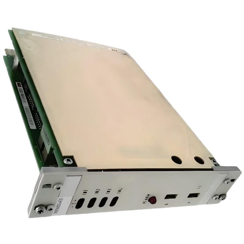
ABB 70EA02A-ES Input Module Fault Diagnosis: Start With the Signal
ABB 70EA02A-ES input faults should be investigated by separating the field signal from the module and System Configuration. When a process value is frozen, low, unstable, or missing, the first question should be whether the expected 4–20 mA signal actually reaches the input channel.
ABB 70EA02A-ES Input Module Fault Symptoms
- One analog channel shows zero or an unexpectedly low value.
- The DCS value remains fixed while the field process changes.
- The input value fluctuates even though the transmitter is stable.
- Several channels show abnormal values simultaneously.
- A channel does not respond correctly during loop simulation.
- The module reports an abnormal status while other rack modules remain operational.
The number of affected channels is an important diagnostic clue. A single abnormal channel points toward the transmitter, field wiring, terminal connection, or individual input path. Several channels failing together should move the investigation toward common power, rack, communication, or module-level causes.
ABB 70EA02A-ES Troubleshooting Decision Process
A common field mistake is to replace the input module immediately after seeing an incorrect DCS value. A more reliable Fault Diagnosis process follows the signal path from the instrument toward the controller.
- Check the process transmitter locally.
- Measure the actual loop current.
- Compare field-side and cabinet-side measurements.
- Check the input channel indication.
- Compare the physical channel with the System Configuration.
- Inspect rack power and module seating.
- Validate the DCS engineering value and scaling.
ABB 70EA02A-ES 4–20 mA Signal Analysis
For a conventional linear 4–20 mA transmitter, approximately 4 mA corresponds to the low end of the configured range and approximately 20 mA corresponds to the high end. This relationship provides a simple reference during Troubleshooting.
DIAGNOSTIC CHECK

measure loop_current

if loop_current < expected_low:
    check transmitter_power
    check field_wiring
    check terminal_connections

if loop_current is stable:
    compare cabinet_signal with DCS_value

if cabinet_signal is correct and DCS_value is incorrect:
    inspect System Configuration
    inspect channel_assignment
    inspect input_processing

if multiple_channels_fail:
    inspect rack_power
    inspect module_status
    inspect common_system_path
ABB 70EA02A-ES Field Fault Investigation Pattern
Consider a practical commissioning fault pattern in which one pressure transmitter appears normal locally but the corresponding DCS value remains near the bottom of its range. Instead of changing the module first, the technician measures the loop current at the cabinet. If the measured current is stable at approximately 12 mA while the DCS value does not represent the expected mid-range signal, the investigation shifts away from the transmitter and toward channel assignment, scaling, or the input processing path.
This diagnostic approach is valuable because it prevents a good input module from being replaced simply because the displayed process value is wrong. The same logic can be applied to flow, temperature, and level transmitters.
ABB 70EA02A-ES Unstable Input Troubleshooting
An unstable value requires a different diagnostic path from a completely dead channel. Start by determining whether the electrical current itself is unstable. If the measured current changes together with the DCS value, investigate the transmitter, field power, cable shielding, grounding, and process signal. If the current remains steady but the DCS value moves significantly, focus on the input channel and system-side processing.
- Check cable routing near variable-speed drives and switching equipment.
- Inspect shield termination and cabinet grounding.
- Check loose or oxidized terminals.
- Compare the field current with the DCS trend.
- Check whether multiple analog channels exhibit the same disturbance.
ABB 70EA02A-ES Low or Missing Input Fault Diagnosis
A low current signal should not automatically be interpreted as an input-module failure. A broken conductor, incorrect transmitter supply path, failed field instrument, or incorrect polarity can produce a similar symptom.
If the measured loop current is close to zero, investigate the field circuit first. If the transmitter produces the expected current but the cabinet does not receive it, inspect the cable and termination. If the cabinet receives the correct current but the DCS remains incorrect, continue with channel-level Troubleshooting.
ABB 70EA02A-ES Module-Level Troubleshooting
After the field signal has been proven correct, inspect the physical input module. Check whether the module is correctly seated, whether the connector is secure, and whether the channel status corresponds to the expected operating condition.
When several input channels fail simultaneously, avoid spending excessive time replacing individual field instruments. A common failure affecting multiple channels is more consistent with a shared system path, power problem, rack issue, configuration error, or module-level fault.
ABB 70EA02A-ES Repair and Replacement Strategy
Repair decisions should be based on evidence collected during Fault Diagnosis. Before replacing a suspected module, record the original channel values, measured loop currents, rack position, alarm information, and System Configuration. This creates a useful reference for verifying the replacement.
- Document the original fault condition.
- Record measured field currents.
- Confirm the physical module identification.
- Compare the replacement hardware identification with the original.
- Install the replacement according to the approved maintenance procedure.
- Repeat the same signal tests after replacement.
- Confirm the DCS value, alarms, and control response.
ABB 70EA02A-ES Post-Repair Commissioning Checks
After a suspected module has been replaced, the work is not complete when the channel starts displaying a value. The technician should verify low-range, mid-range, and high-range signal behavior and confirm that the value is correctly associated with the intended process tag.
For control applications, also verify alarm thresholds and downstream logic. A correctly measured analog signal can still cause an operational problem if the engineering range or alarm configuration is wrong.
ABB 70EA02A-ES Troubleshooting and Fault Diagnosis FAQ
Why does the ABB 70EA02A-ES show an incorrect process value?
The cause may be in the transmitter, field wiring, input channel, or System Configuration. The fastest separation method is to compare the actual loop current with the value received by the DCS.
What should be checked when one 70EA02A-ES channel stops responding?
Check the transmitter output, loop continuity, terminal connections, channel indication, physical module seating, and channel assignment before replacing the module.
Why are several ABB 70EA02A-ES channels failing at the same time?
Multiple simultaneous failures suggest investigating common causes such as rack power, module condition, shared wiring, system communication, or configuration rather than assuming several field transmitters failed independently.
How can an unstable 4–20 mA signal be diagnosed?
Measure the current independently while observing the DCS trend. If both measurements fluctuate together, investigate the transmitter and field circuit. If the current is stable but the DCS value fluctuates, investigate the input path and configuration.
Can incorrect scaling look like an ABB 70EA02A-ES hardware fault?
Yes. A stable electrical signal can produce an incorrect engineering value when the configured range, channel assignment, or engineering-unit conversion does not match the transmitter.
What does a near-zero input signal indicate?
A near-zero signal can result from a transmitter fault, broken loop, incorrect wiring, loss of loop power, or another field-side problem. Direct current measurement should be performed before identifying the input module as defective.
When should an ABB 70EA02A-ES module be considered for replacement?
Replacement becomes more reasonable after the field transmitter, wiring, measured loop current, channel configuration, rack conditions, and connector have been checked and the abnormal behavior remains isolated to the module.
What information should be recorded before replacing the input module?
Record the module identification, rack position, affected channel, measured loop current, DCS value, alarm condition, System Configuration, and any relevant trend information. These records make post-replacement verification much more reliable.
ABB 70EA02A-ES Troubleshooting Guide Final Summary
Effective ABB 70EA02A-ES Troubleshooting depends on separating the field instrument, electrical loop, input module, and DCS configuration instead of treating every abnormal value as a hardware failure. A measured 4–20 mA signal provides the most useful starting point for Fault Diagnosis. Once the electrical signal is proven, channel configuration, rack conditions, module status, and engineering scaling can be investigated systematically, reducing unnecessary module replacement and shortening maintenance time.



