100% Original, Ready to Ship!

ABB SS822 3BSC610042R1 Power Voting Unit Troubleshooting Guide

ABB SS822 3BSC610042R1 Power Voting Unit Fault Diagnosis
ABB SS822 3BSC610042R1 Power Voting Unit faults commonly appear as DC power instability, an abnormal input supervision indication, unexpected loss of the redundant power path, or an output voltage problem. Before replacing the module, technicians should determine whether the fault originates from an upstream SD821, SD822, or SD823 power supply, an input wiring connection, excessive load current, or the SS822 itself.
The ABB SS822 is designed to combine two independent 24 V DC power inputs into one redundant power output. Each input is supervised separately, making input-side measurements particularly important during Troubleshooting. A systematic Fault Diagnosis process can prevent unnecessary module replacement and reduce downtime in ABB industrial control systems.
ABB SS822 Power Voting Unit Failure Symptoms
When an SS822-related problem occurs, the first indication may come from the front-panel LEDs or the connected control system’s power supervision circuit.
Common field symptoms include:
- One input supervision LED is not illuminated.
- The control cabinet reports a power supply failure.
- The redundant power arrangement operates from only one source.
- The output voltage falls below the expected operating level.
- The voltage-free supervision contact changes state unexpectedly.
- The downstream PLC or I/O equipment experiences intermittent power interruptions.
- The power voting unit becomes unusually warm under sustained load.
These symptoms do not necessarily indicate an internal SS822 failure. A defective upstream power supply or a loose DC terminal can produce similar behavior.
ABB SS822 Fault Diagnosis: Start with Input Measurements
One of the most useful troubleshooting techniques is to divide the circuit into three measurement areas: input A, input B, and the common output. This approach avoids replacing the complete power voting unit before identifying the actual fault location.
Input A and Input B Voltage Inspection
Use a calibrated digital multimeter to measure each input independently. Record the measurements under normal operating conditions and compare them with the corresponding power supply output terminals.
| Inspection Point | Expected Condition | Possible Fault Indication |
|---|---|---|
| Input A | Nominal 24 V DC | Low or unstable supply voltage |
| Input B | Nominal 24 V DC | Missing redundant source |
| Output | 24 V DC nominal | Voltage drop or overload |
| Input A LED | Normal voltage supervision | Input A supervision fault |
| Input B LED | Normal voltage supervision | Input B supervision fault |
| Supervision Contact | State consistent with input condition | Alarm wiring or contact problem |
Do not use the nominal voltage alone to determine whether the unit is defective. The SS822 has factory-set supervision thresholds that must also be considered.
Common ABB SS822 3BSC610042R1 Power Fault Causes
Unstable 24 V DC Input Supply
An upstream SD821, SD822, or SD823 power supply may produce unstable output voltage because of an internal fault, overload, poor AC input conditions, or excessive temperature. If the SS822 indicates an input problem, measure the voltage directly at the power supply output before disconnecting the voting unit.
Incorrect DC Polarity or Loose Terminals
Loose terminal connections can create intermittent voltage drops, particularly when the connected equipment draws a high current. Inspect the positive and negative connections, conductor condition, and terminal tightness against ABB specifications.
Excessive Output Load
The SS822 has a rated output current of 20 A. If the connected load exceeds the available power capacity, output voltage instability may occur. Check the total current demand rather than assuming that the voting unit is defective.
Supervision Contact Wiring Problems
The SS822 uses voltage-free supervision contacts. An incorrect connection to a PLC digital input, incorrect contact logic, or damaged monitoring cable can generate a false power failure alarm even when the DC output remains normal.
High Cabinet Temperature
Heat dissipation increases with output current. The documented heat dissipation is approximately 10 W at 20 A. Poor ventilation or excessive cabinet temperature can affect the operating conditions of the power system.
ABB SS822 Power Voting Unit Diagnostic Logic
Rather than replacing components immediately, use the following fault isolation logic to identify the affected section.
Diagnostic Reference Values
| Supervision Parameter | ABB SS822 Value |
|---|---|
| Low-voltage trip threshold | 22 V |
| Low-voltage hysteresis | 0.7 V |
| High-voltage trip threshold | 30 V |
| High-voltage hysteresis | 0.7 V |
| Nominal DC input | 24 V |
| Rated output current | 20 A |
The trip thresholds are factory preset. A voltage below 22 V during decreasing voltage or above 30 V during rising voltage can cause the corresponding supervision condition to change. Hysteresis prevents repeated switching around a threshold.
Practical Troubleshooting Decision Sequence
- If input A is abnormal, inspect the first power supply and its wiring.
- If input B is abnormal, inspect the second power supply and its wiring.
- If both inputs are normal but the output is abnormal, inspect the output terminals and downstream load.
- If the output voltage is normal but a PLC alarm remains active, inspect the supervision contacts and monitoring logic.
- If all external conditions are correct but the fault persists, investigate possible internal SS822 damage.
ABB SS822 Power Supply Troubleshooting with Diagnostic Commands
The SS822 does not have a conventional programmable firmware diagnostic interface. The following pseudocode is intended as a maintenance checklist or PLC-side diagnostic concept, not as executable ABB SS822 commands.
IF Input_A_Voltage < 22.0 THEN
    Alarm_Input_A = TRUE;
END_IF;

IF Input_B_Voltage < 22.0 THEN
    Alarm_Input_B = TRUE;
END_IF;

IF Output_Voltage < Required_System_Voltage THEN
    Alarm_Output_Power = TRUE;
END_IF;

IF Input_A_OK = FALSE AND Input_B_OK = FALSE THEN
    Alarm_Redundant_Power_Lost = TRUE;
END_IF;
These examples require suitable external voltage-monitoring signals and application-specific PLC logic. The SS822 supervision contacts should be connected and interpreted according to the actual circuit design. They do not provide direct numerical voltage measurements to the PLC.
ABB SS822 Realistic Field Fault Investigation
Illustrative troubleshooting case: An ABB control cabinet reports a redundant power supply alarm even though the connected PLC and I/O equipment remain operational.
The maintenance engineer initially suspects an internal failure of the SS822. However, the first diagnostic inspection shows that input A measures 24.1 V DC while input B measures 21.6 V DC.
Since the SS822 low-voltage supervision threshold is 22 V during decreasing voltage, the second input requires immediate investigation. The engineer then measures the voltage at the output terminals of the second upstream power supply and finds a similar low reading.
Instead of replacing the SS822, the engineer checks the upstream SD822 supply, its AC input, output terminals, and connected load. After correcting the external supply problem, the input voltage returns to its normal operating range and the corresponding supervision indication recovers.
Engineering conclusion: The alarm originated from the upstream power source rather than the power voting unit. This type of diagnostic separation is important because an input supervision alarm should not automatically be treated as evidence of internal SS822 failure.
ABB SS822 Output Voltage and Redundancy Failure Analysis
If both input supplies appear normal but the common output remains unstable, additional measurements are necessary.
Check the Output Voltage Drop
Measure the output voltage directly at the SS822 terminals and compare it with the input voltage. At maximum rated current, the documented output regulation indicates approximately 0.5 V below the input voltage. A larger unexpected difference should lead to an inspection of the wiring, load, and terminal connections.
Investigate Single-Source Operation
When one power source becomes unavailable, the remaining input should be evaluated against the actual connected load. A redundant system cannot maintain the required output if the remaining supply is undersized or defective.
Inspect the Supervision Circuit
The SS822 supervision contacts have defined electrical ratings:
- AC contact rating: Maximum 120 V and 0.5 A.
- DC contact rating: Maximum 28 V and 1 A.
- Minimum DC contact load: 1 mA.
- Recommended minimum DC contact load: 5 mA.
Check that the monitoring circuit operates within these limits. Incorrect contact loading can create misleading alarm behavior.
ABB SS822 Repair and Replacement Evaluation
Internal repair should only be considered after external electrical problems have been excluded. The SS822 is part of a power distribution and redundancy arrangement, so an incorrect repair can introduce a new failure into an otherwise operational control cabinet.
Before replacing the ABB 3BSC610042R1 module, complete the following inspection:
- Verify both 24 V DC input sources.
- Inspect all input and output connections.
- Measure the connected load current.
- Check for signs of overheating or physical damage.
- Verify the front-panel supervision indications.
- Test the associated voltage-free contacts.
- Confirm that the correct product model and revision are installed.
If internal damage is suspected, remove the device under an approved isolation procedure and arrange assessment by qualified industrial electronics personnel. Do not attempt component-level repair while the unit is energized.
ABB SS822 Troubleshooting FAQ
Why does the ABB SS822 show a power supply fault when the output is still available?
The SS822 monitors its two input supplies independently. One input can become abnormal while the second source continues supplying the connected load. Check both input voltages and their supervision indications.
What is the low-voltage alarm threshold of ABB SS822?
The factory-set low-voltage trip threshold is 22 V during decreasing voltage, with 0.7 V hysteresis. This value is useful when investigating unstable 24 V DC power sources.
Can a defective SD822 cause an SS822 fault alarm?
Yes. A defective upstream SD822 can produce an abnormal input voltage, causing the corresponding SS822 supervision circuit to report a fault.
Why does the SS822 output voltage measure lower than 24 V DC?
The output voltage can be approximately 0.5 V below the input voltage at maximum rated current. Cable resistance, terminal conditions, and load demand should also be checked before concluding that the unit is defective.
Does ABB SS822 have an internal communication fault?
The SS822 is a power voting device rather than a conventional communication module. Most related alarms involve power input supervision or external monitoring circuits rather than fieldbus communication.
What causes both SS822 input supervision indications to become abnormal?
Possible causes include loss of the common upstream AC supply, failure of both DC power sources, incorrect wiring, or abnormal input voltage. Measure each supply independently to identify the actual cause.
Can the ABB SS822 be replaced without checking the connected load?
This is not recommended. Confirm that the connected load remains within the rated 20 A output capacity and that the replacement device matches the existing hardware requirements.
When should the ABB SS822 Power Voting Unit be replaced?
Replacement should be considered when internal malfunction is confirmed after verifying the upstream supplies, input wiring, output connections, load current, and supervision circuits. Physical damage or persistent abnormal operation under verified electrical conditions also warrants further evaluation.
ABB SS822 Fault Diagnosis: Final Maintenance Summary
Effective ABB SS822 3BSC610042R1 Troubleshooting requires separating upstream power supply faults from voting-unit faults. The most reliable diagnostic approach is to measure both 24 V DC inputs, inspect the common output, verify the supervision contacts, and evaluate the connected load before considering hardware replacement.
For maintenance teams working with ABB AC 800M and industrial control power systems, keeping detailed voltage measurements and alarm records can make future Fault Diagnosis considerably faster. The SS822 should be evaluated as part of the complete redundant power architecture rather than as an isolated component.
Always follow ABB technical documentation, electrical isolation procedures, and site-specific maintenance requirements when inspecting or replacing the Power Voting Unit.
 ABB NE810 3BSE080207R1 Industrial Ethernet Switch Troubleshooting Guide
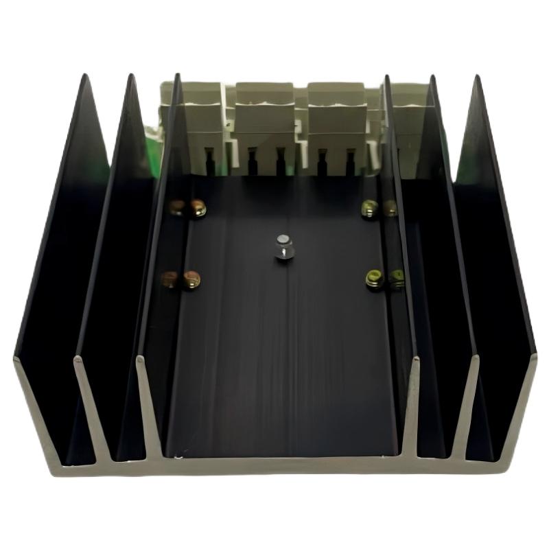 ABB SS110 3BSE007698R1 Voting Unit Troubleshooting Guide
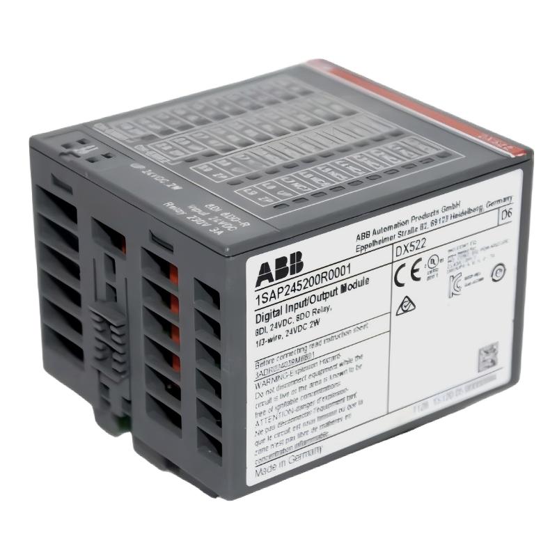 ABB DX522 1SAP245200R0001 Digital I/O Module Troubleshooting Guide
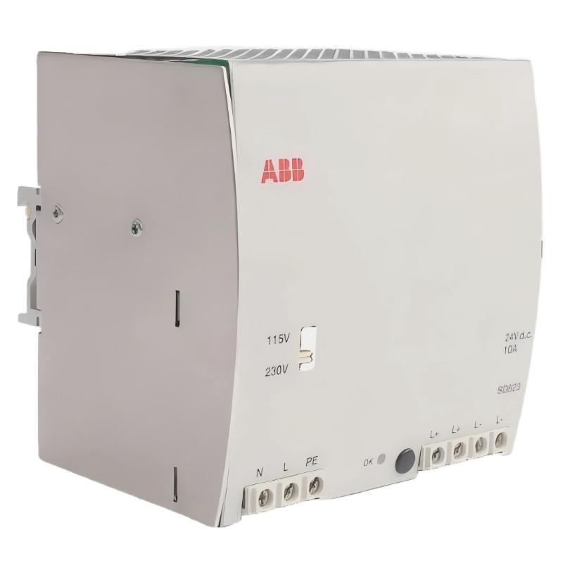 ABB SD823 3BSC610039R1 Power Supply Troubleshooting Guide