Table of Contents
- ABB 1VCF309499S0012 Control Module Feeder Overview
- Installation Preparation and System Configuration
- ABB 1VCF309499S0012 Wiring and Connection Procedure
- Setup and Commissioning Validation
- Field Commissioning Experience
- ABB 1VCF309499S0012 Installation FAQ
- General Overview
ABB 1VCF309499S0012 Control Module Feeder Installation Guide Overview
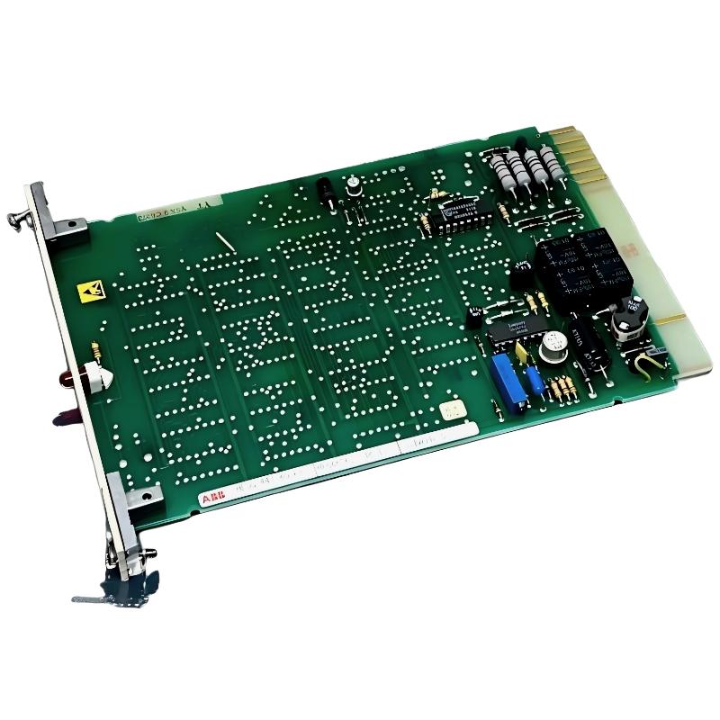
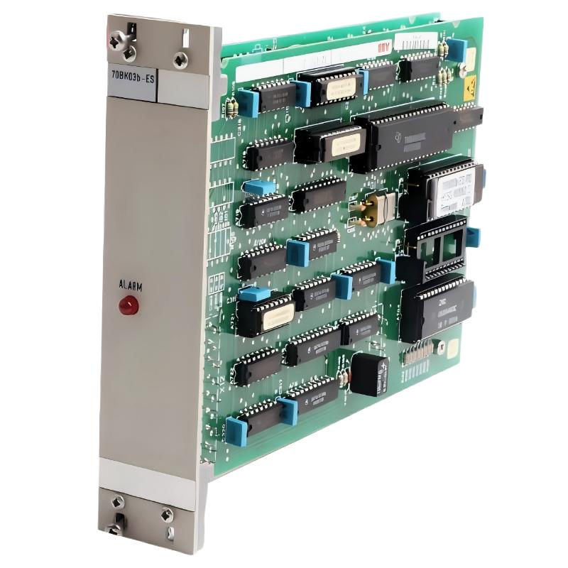
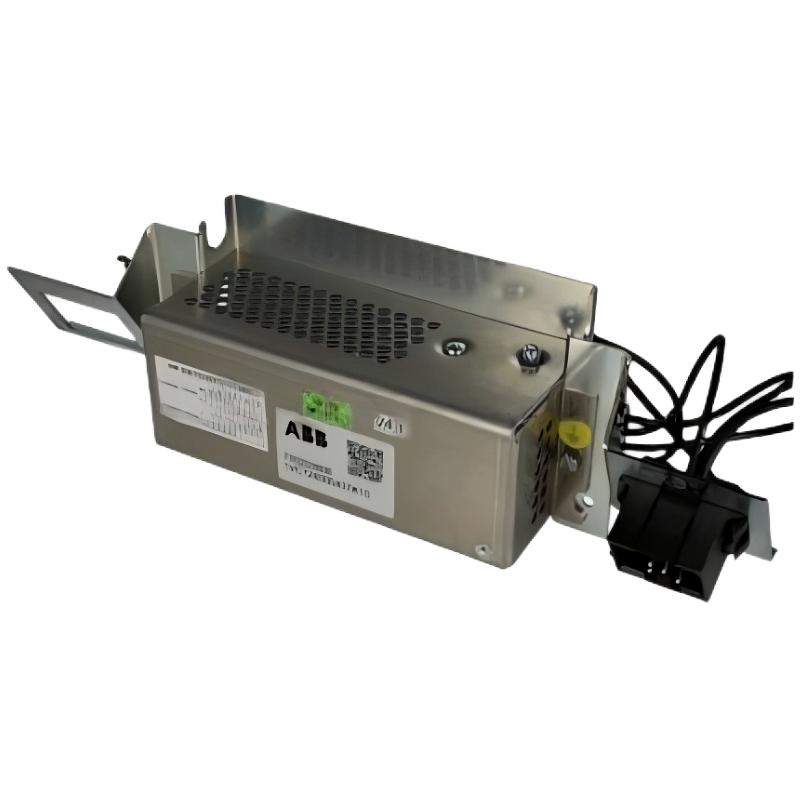
ABB 1VCF309499S0012 Control Module Feeder installation requires correct auxiliary power verification, wiring inspection, and commissioning testing before integration into a V/Contact or V/ZVC medium voltage control system. This feeder module is designed for AU-TR auxiliary voltage applications with 100-250Vdc/ac supply range, providing the control power interface required for compatible ABB contactor systems.
During field installation, engineers should treat the ABB 1VCF309499S0012 as a critical control module rather than a simple power accessory. Incorrect polarity, unstable auxiliary voltage, or poor terminal connections can create abnormal closing or opening behavior in the switching system.
ABB 1VCF309499S0012 Module Preparation Before Installation
Before starting the Setup and Commissioning process, verify the complete System Configuration and ensure the replacement part matches the original feeder module specification.
- Confirm ABB 1VCF309499S0012 model identification.
- Check auxiliary voltage availability between 100-250V AC/DC.
- Inspect terminal blocks for oxidation or mechanical damage.
- Verify grounding condition of the control cabinet.
- Review existing control logic before removing the old module.
A common engineering mistake is replacing the feeder module without recording the original wiring arrangement. This can introduce commissioning delays because control signals may appear incorrect even when the hardware is healthy.
ABB 1VCF309499S0012 Control Module Feeder Wiring Procedure
The ABB 1VCF309499S0012 Installation Guide process should follow electrical safety procedures. Disconnect auxiliary power before terminal work and confirm zero voltage conditions.
- Remove the previous feeder module carefully.
- Compare terminal positions between old and new modules.
- Connect auxiliary supply wiring according to the cabinet diagram.
- Check control circuit continuity.
- Secure the module mechanically before energizing.
Recommended field verification:
Measure auxiliary input voltage:
Vaux = 100-250 VAC/DC

Check continuity:
Terminal A ---- Control Circuit ---- Terminal B

Verify insulation:
Resistance > acceptable site standard
ABB 1VCF309499S0012 Setup and Commissioning Validation
After installation, the commissioning engineer should perform functional tests instead of only checking power availability.
- Confirm auxiliary voltage stability.
- Test contactor command response.
- Observe opening and closing sequence.
- Monitor abnormal heating or noise.
A successful Setup and Commissioning process requires both electrical measurement and operational confirmation.
ABB 1VCF309499S0012 Real Field Commissioning Case
In one medium voltage panel retrofit project, an ABB 1VCF309499S0012 Control Module Feeder was installed as a replacement unit. Initial testing showed intermittent contactor operation even though the measured input voltage was 230VAC.
The engineering team checked the complete control path instead of replacing the module again. We observed that the terminal connection resistance was higher than expected due to loose compression. After retightening the terminals, the voltage drop during operation decreased from approximately 18V to less than 2V, and the contactor completed more than 50 switching cycles without interruption.
ABB 1VCF309499S0012 Installation FAQ
What voltage range does ABB 1VCF309499S0012 support?
ABB 1VCF309499S0012 is designed for AU-TR auxiliary voltage applications with 100-250Vdc/ac supply requirements used in compatible ABB V/Contact and V/ZVC systems.
Why should wiring inspection be performed before commissioning?
Incorrect terminal connection or unstable auxiliary power can create symptoms similar to a faulty control module. Field diagnosis should always verify the electrical path first.
Can this module be replaced during system maintenance?
Yes, replacement is commonly performed during planned maintenance, but engineers should complete isolation procedures and verify the complete control circuit before operation.
General Overview of ABB 1VCF309499S0012 Control Module Feeder
The ABB 1VCF309499S0012 Installation Guide process focuses on correct auxiliary power connection, reliable wiring, and practical commissioning validation. A professional installation approach reduces unexpected feeder failures and improves the long-term stability of medium voltage control systems.